9
POWER MAX
100 - 110 - 130 - 150
1
3
4
5
14
17
2
21
22
13
109 11 12
1
2
3
4
5
6
7
8
19
23
14
21
20
22
16
17
15
18
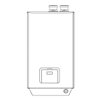
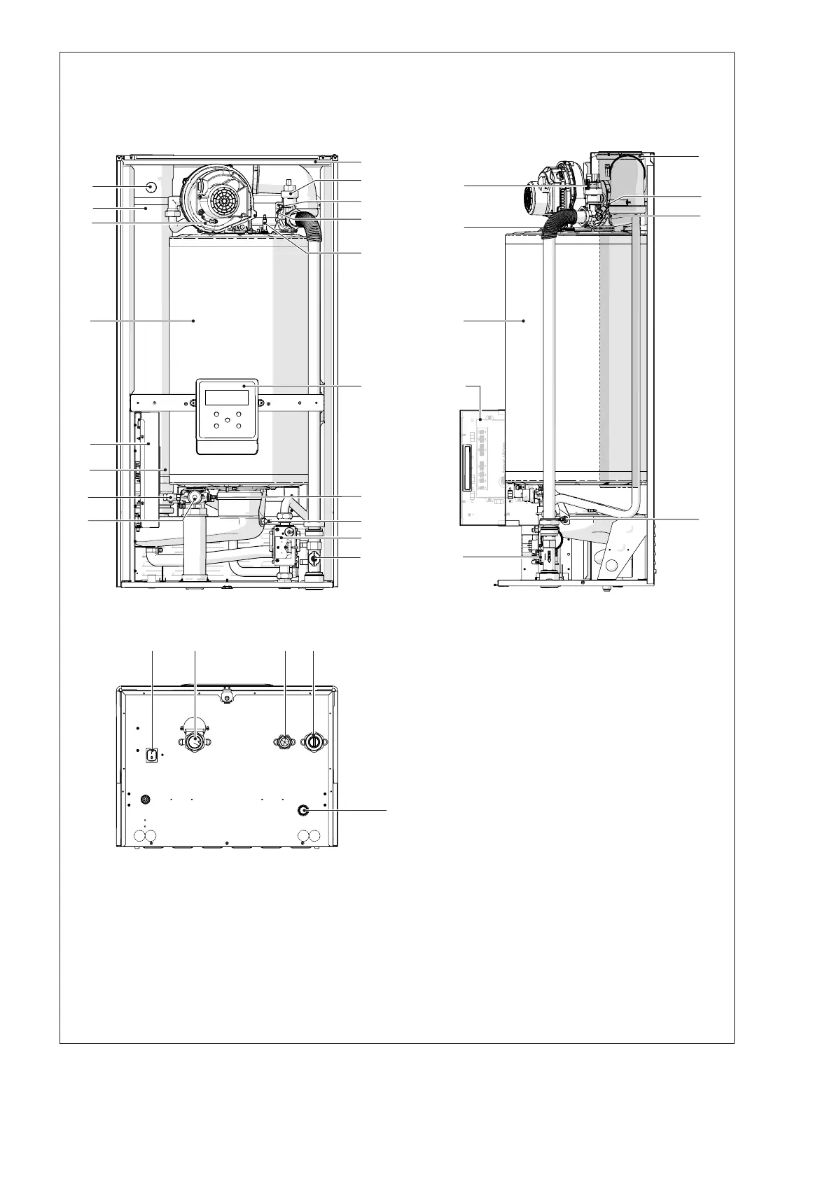
1
Flue gas analysis outlet
2
Flue gas exhaust connection
3
Fan
4
Combustion chamber
5
Electrical panel
6
Smoke-exhaust ue non-return valve
7
Drain cock
8
Minimum Pressure Switch set at 0,7 bar
9
Main switch
10
Central heating return
11
Gas supply
12
Central heating ow
13
Condensate drain connection
14
Flow-meter
15
Gas valve
16
Exhaust ue probe
17
Return probe
18
Control panel
19
Ignition/detection electrode
20
Safety Thermostat with manual reset by PCB
21
Flow probe
22
Automatic bleed valve
23
Casing
 Loading...