2.3 Mounting
CAUTION
The WS5-5 must be housed in a
switch cabinet so as to ensure resist-
ance to interference and prevent the
equipment from being contaminated.
Make sure that there are adequate pro-
visions for the dissipation of heat!
The equipment is fitted to a supporting rail on the
mounting wall by means of the fasteners at the
back of the equipment and is secured at the sides
by the end brackets. The minimum clearance be-
tween several WS5 units or from other pieces of
equipment must be 10 cm. The outer surfaces of
the equipment act as a heat sink to remove the
heat. The maximum power dissipation of the equip-
ment is 80 W.
2.4 Cabling
2.4.1 General instructions
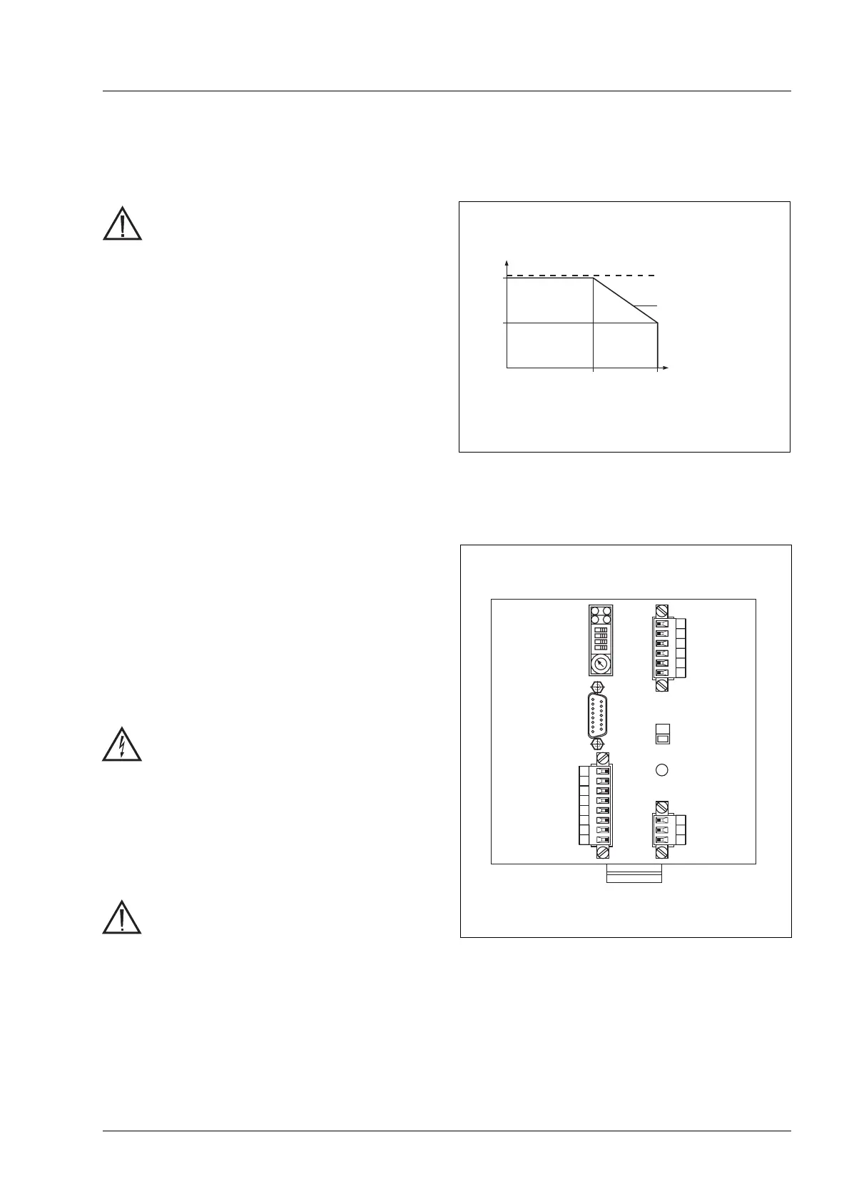
All the electrical connections will be made by multi-
pole plug connections on the front panel of the
equipment (Figure 2-3). Ready-made cables are
available as accessories (see section 2.2).
DANGER
•
Switch off mains voltage before con-
necting cables!
•
The power connections (motor,
mains) should be carried out only by
qualified electrical engineers in ac-
cordance with VDE 0105!
CAUTION
•
Make sure that the cables are
screened and fitted with strain-relief
clamps!
•
Twist every pair of signalling cables
before connecting them!
•
Lay mains, motor and signal cables
so that there is a space between
them!
230V
Motor
connection
Mains
connection
Signal
interface1
Signal
interface2
Figure 2-3 Overview of connections
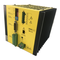
T
am
= ambient temperature
I
phase
= phase current
T
am
[˚C]
Forced cooling ≥ 1m/s
Convection cooling
I
phase
[A]
50
25
1,6
2,8
Figure 2-2 Cooling
Installation
WS5-5 Doc. no. 211.347/DGB 03.96 2 – 3
 Loading...