2.4.5 Connection of the signal cables
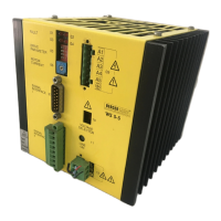
Signal cable of signal interface 1
1. Twist the wires of the signal cable for signal
interface 1 in pairs and solder to the terminals of
the 15-pole sub-D socket connector strip as
shown in Figure 2-8.
2. Insert cable underneath the strain relief clamp
and secure. Connect screen to earth (GND) on
control side.
NOTE
When using a push-pull drive, it may
be useful to connect the screen to the
plug shell on both ends of the cable.
3. Fit socket shell.
4. Plug socket to socket connector strip 07, and
screw tight.
CAUTION
•
For maximum cable length to signal
interface 1, see standard for RS 422
interfaces.
•
All signal connections must be safely
isolated from the mains.
•
The earth (GND) of signal interfaces
1 and 2 is connected internally to the
protective conductor.
•
It is not permitted to apply a voltage
between earth (GND) and protective
conductor in order to avoid damage.
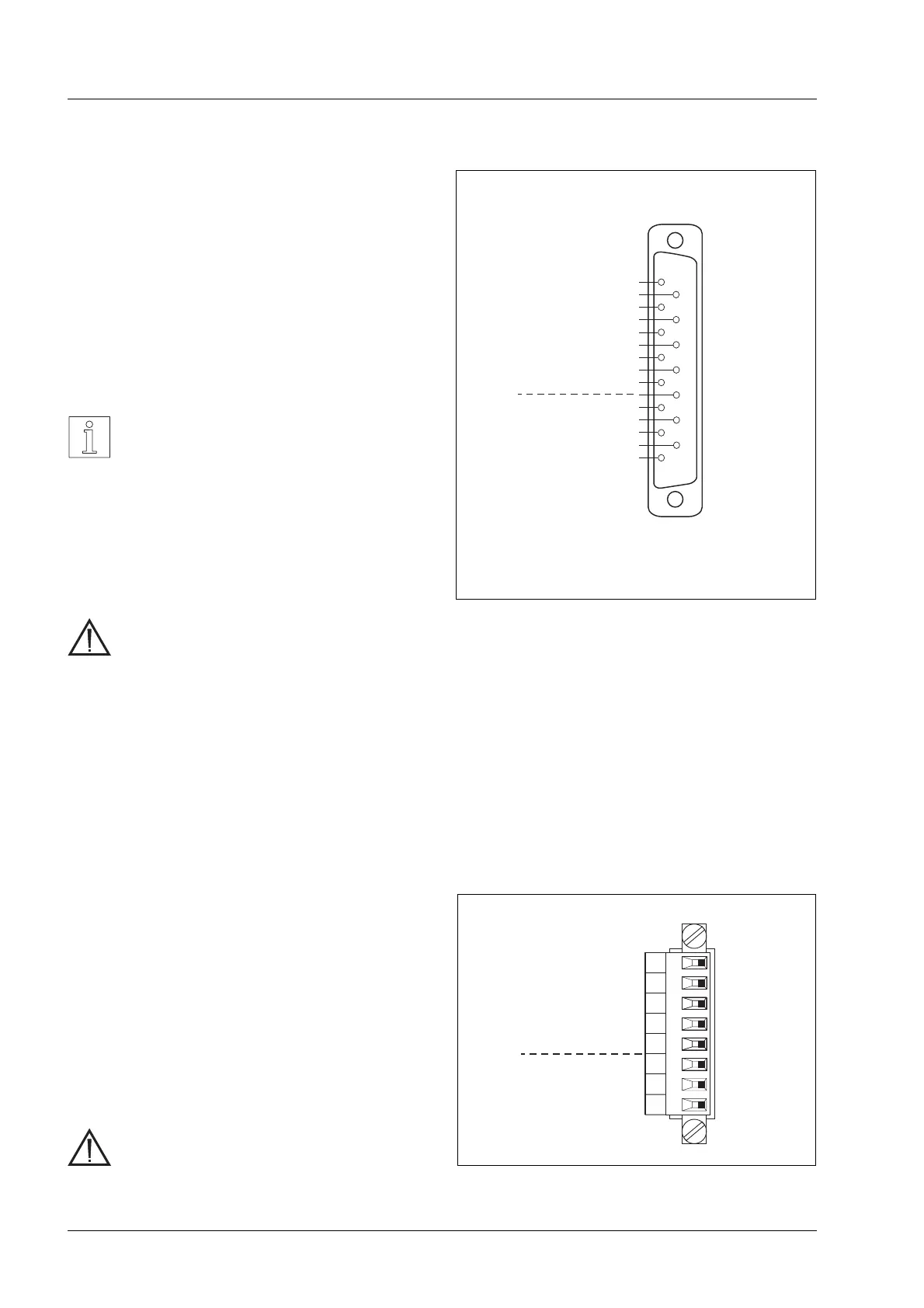
Signal cable of signal interface 2
1. Prepare the 8 wires of the signal cable for signal
interface 2 and fit to plug with boot lace ferrules.
2. Insert the wires into mating plug terminal block as
shown in Figure 2-9 and screw tight.
3. Join the plug shell halves together.
4. Fit plug to terminal 08 and screw tight.
CAUTION
•
Maximum length of signal cable:
50 m.
1
2
3
4
5
6
7
8
9
10
11
12
13
14
15
PULSE
PULSE
DIRECTION
DIRECTION
ENABLE
ENABLE
PWM/BOOST
PWM/BOOST
GND
READY
READY
GND
READY*
+
-
+
-
+
-
+
-
+
-
07
OPEN COLLECTOR output (npn)
I
max
=10mA
U
CEsat
≤1.2V
(short-circuit-proofup to6 V)
*
InputsOutputs
Figure 2-8 Connector pin assignment for signal
interface 1
8
7
6
5
4
3
2
1
GND
READY
READY
ZERO PHASE
ZERO PHASE
PWM/BOOST
GATE
ENABLE
-
+
-
+
08
OutputsInputs
Figure 2-9 Connector pin assignment for signal
interface 2
Installation
2 – 6 WS5-5 Doc. no. 211.347/DGB 03.96
 Loading...