3 Operation
The power drive WS5-5 is operated by means of
control signals. It can be linked to the external con-
troller via signal interfaces 1 and/or 2.
3.1 Signal Description
The meanings and functions of the individual sig-
nals are described below.
3.1.1 Input signals
NOTE
An ’active’ input means a flow of cur-
rent from + to -, an ’inactive’ input
means a flow of current from - to + or
no current at all.
PWM/BOOST (Current control/Current increase)
Input for pulse width modulated signal (PWM) for
phase current control, current zero-setting or for the
boost function.
• Parameter switch 05/01 OFF and input ’active’:
Current zero-setting activated;
• Parameter switch 05/01 OFF and PWM signal at
the input:
Controller of the phase current activated. When
the PWM signal is active, the motor current amo-
unts to between 0 and 100% of the preset phase
current. The frequency range of the PWM signal
shall lie between 10 and 20 Hz.
• Parameter switch 05/01 ON and input ’active’:
Boost function activated. The motor current is
raised to twice the preset phase current, but to a
maximum of 2.8 A.
CAUTION
• Increasing the current by the boost
function to beyond the rated current
of the motor is only permitted
momentarily (20% of the motor duty
cycle, maximum 10 s).
• The boost function must not be acti-
vated for the motors ExRDM
5913/50P and ExRDM 599/50P.
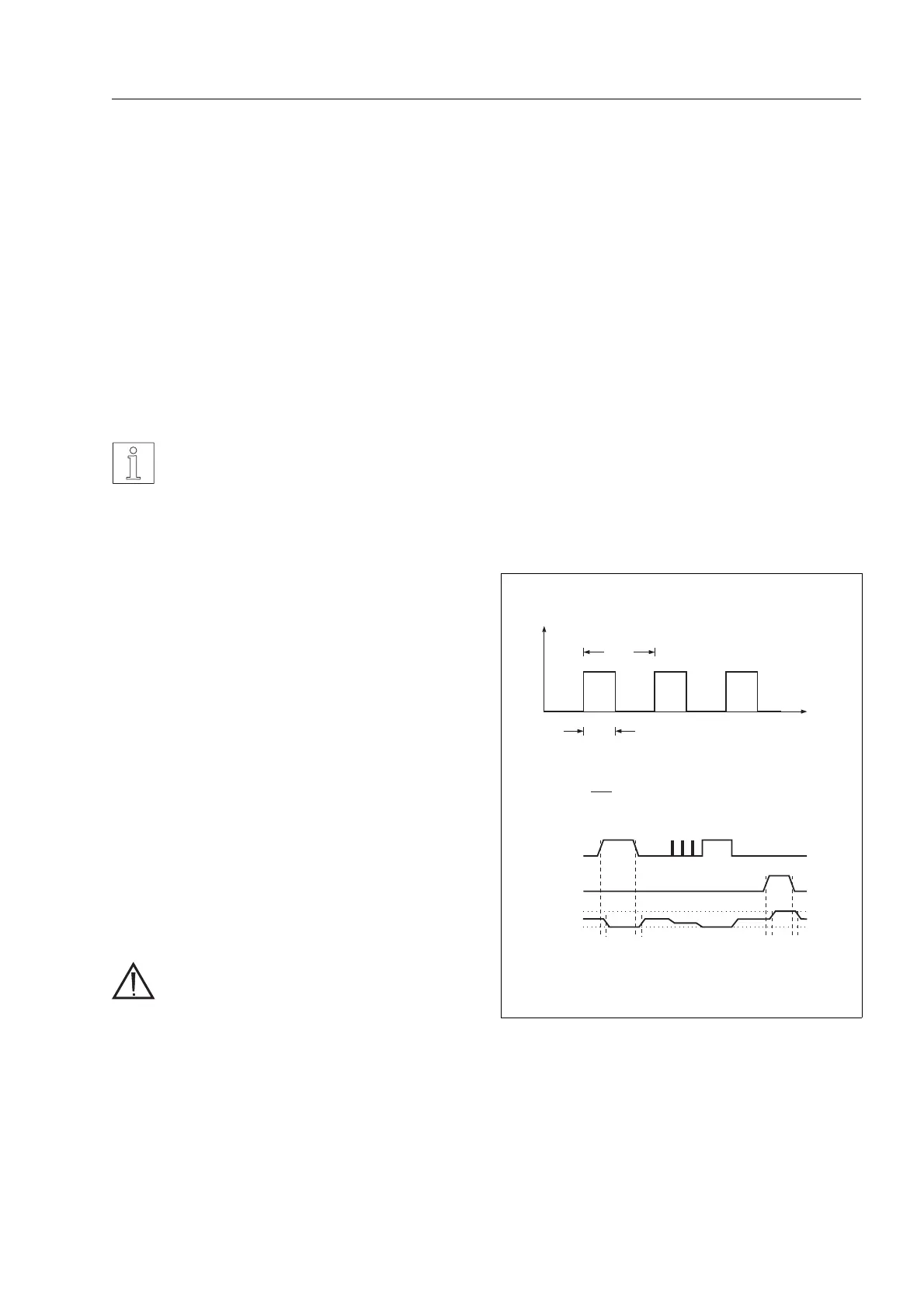
PWM/BOOSTinput
t
ein
t
ein
τ=1/f
f=pulsefrequency =10....20 kHz
I
0
=presentvalue ofthephase current
I
ph
=(1- )·I
0
(PWMactive)
τ
PWM
BOOST
I
Ph
t
1
t
2
t
3
t
4
2I
0
0
t
1
=t
2
=t
3
=t
4
=1ms(typ.)
Figure 3-1 Phase current control
Operation
WS5-5 Doc no. 211.347/DGB 12.92 3 – 1
 Loading...