ENABLE (Enabling Command)
•
Input ’active’: enabling of power drive
•
Input ’inactive’: deletion of a stored fault report
(see section 4.2) and resetting of the ring coun-
ter (see output signal 0-PHASE). The motor is
disconnected from the current.
CAUTION
When the ENABLE input is ’inactive’,
the motor is de-energized, i.e. it has
no stopping torque.
NOTE
If the error message is repeated, dis-
connect the mains voltage and rectify
the fault using the troubleshooting
table (section 4.2).
PULSE (Step)
With each rising signal edge at the PULSE input the
motor executes one step.
NOTE
The maximum pulse frequency is
100 kHz.
DIRECTION (Direction of rotation)
Depending on the position of the parameter switch
05/03 (see Figure 2-14) the inputs have the follow-
ing meaning:
•
Input ’inactive’: Clockwise
(parameter switch OFF)
•
Input active’: Counterclockwise
(parameter switch OFF)
NOTE
Direction of rotation looking at the
motor shaft (flange side). The signal
response times for PULSE and DIREC-
TION are shown in Figure 3-3.
GATE
•
Input ’active’: Pulse input is disabled
•
Input ’inactive’: Pulse input is not disabled
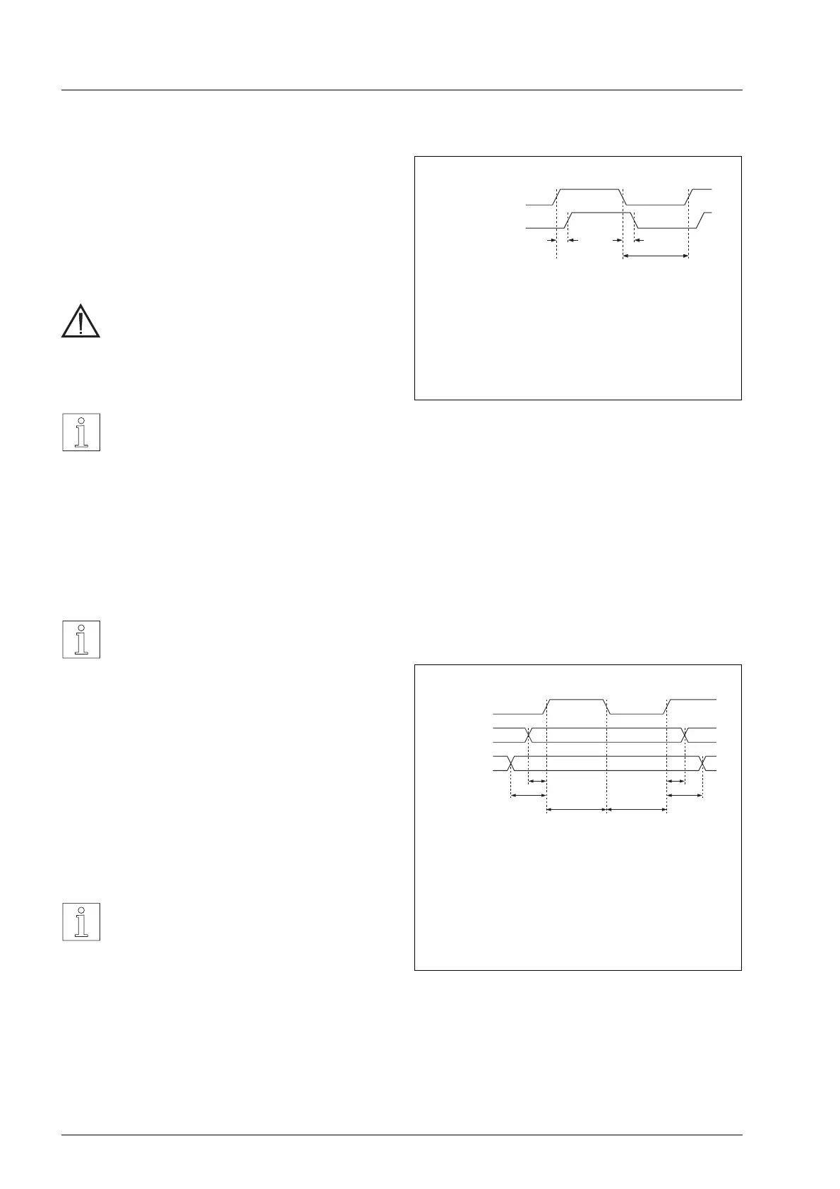
PULSE
DIRECT.
GATE
t
1
≥
t
2
≥
t
3
≥
t
4
≥
t
5
≥
t
6
≥
DIRECTION preparation time
GATE preparation time
DIRECTION stop time
GATE stop time
Pulse length
Pulse interval
0 µs
20 µs
2 µs
0 µs
5 µs
5 µs
t
1
t
2
t
3
t
4
t
5
t
6
Figure 3-3 PULS/DIRECTION/GATE response
times
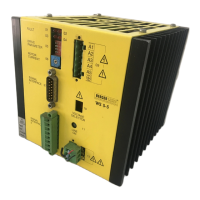
ENABLE
READY
t
1
=t
2
<5ms
t
3
> 100 ms
Switch on/off time
of power stage
Waiting time
for ENABLE
t
1
t
2
t
3
Figure 3-2 ENABLE/READY response times
Operation
3 – 2 WS5-5 Doc no. 211.347/DGB 12.92
 Loading...