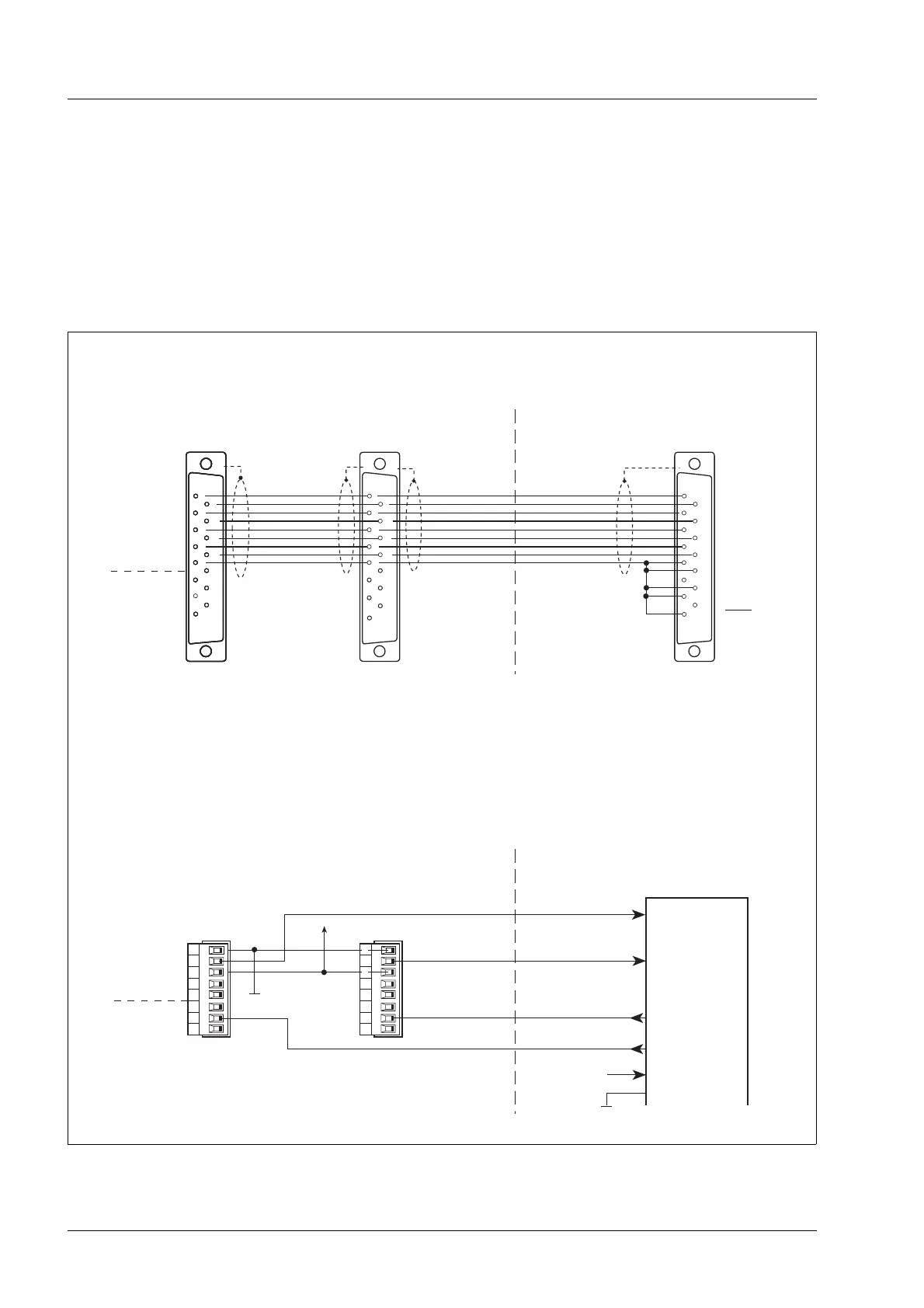
2.4.7.4 Driving of two WS5-5 via WP311
positioning unit from BERGER
Two WS5-5 can be driven via a positioning unit
WP311 in the same way as via a WP111, see chap-
ter 2.4.7.3.
8
7
6
5
4
3
2
1
2
3
4
5
6
8
1
9
10
11
12
13
14
15
*
WS5-5
2
3
4
5
6
8
1
9
10
11
12
13
14
15
2
3
4
5
6
7
8
1
9
10
11
12
13
14
15
2
3
4
5
6
8
1
9
10
11
12
13
14
15
*
2
3
4
5
6
8
1
9
10
11
12
13
14
15
2
3
4
5
6
8
1
9
10
11
12
13
14
15
*
2
3
4
5
6
7
8
1
9
10
11
12
13
14
15
2
3
4
5
6
7
8
1
9
10
11
12
13
14
15
6
7
8
13
14
15
8
7
6
5
4
3
2
1
WS5-5
+24 V
+24 V GND
+24 V
I/O WP311
2
3
4
1
9
10
11
12
5
Sub-D-socket
WS5-5 (axis 1)
GND
- READY
+READY
- ZERO PHASE
+ZERO PHASE
PWM/BOOST
GATE
ENABLE
OutputsInputs
+PULSE
- PULSE
+DIRECTION
- DIRECTION
+ENABLE
- ENABLE
+PWM/BOOST
- PWM/BOOST
GND
+READY
- READY
InputsOutputs
GND
READY
*
OPEN COLLECTOR-output (npn)
I
max
= 10 mA
U
CEsat
≤ 1,2 V (short-circuit-proof up to 6 V)
Positioning unit WP311
Interface 1
Interface 2
Sub-D-socket
+PULSE
- PULSE
+DIRECT.
-DIRECT.
+ENABLE
- ENABLE
+IPWMIN
- IPWMIN
GND
RM FAULT
TEMP. INT.
TEMP. MOT.
GND
READY
WS5-5 (axis 2)
Sub-D-socket
e.g. I 1
Positioning unit WP311
e.g. I 2
e.g. Q 2
e.g. Q 1
I/O Supply
Figure 2-16 Driving of two WS5-5 via WP311
Installation
2 – 12 WS5-5 Doc. no. 211.347/DGB 03.96
 Loading...