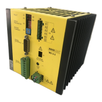
2.4.7.5 Driving via PCL IP 267 from Siemens
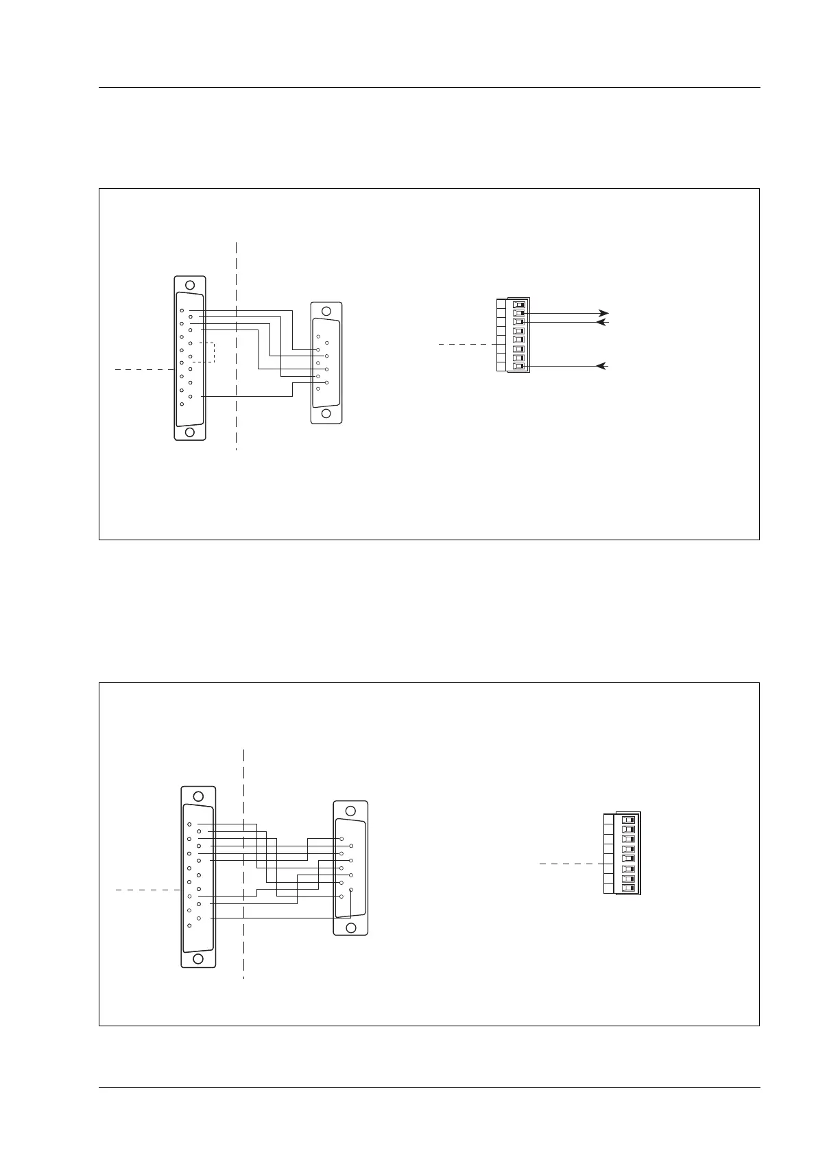
2.4.7.6 Driving via PCL IP 247 from Siemens
8
7
6
5
4
3
2
1
WS5-5
2
3
4
5
6
7
8
1
9
10
11
12
13
14
15
*
WS5-5
2
3
4
5
6
7
8
1
9
10
11
12
13
14
15
2
3
4
5
1
6
7
8
9
**
+24 V
**
Sub-D-socket
TN (clock)
RP (direction level)
RP_N (direction level inverted)
TN_N (clock inverted)
NL (Ground)
GND
- READY
+READY
- ZERO PHASE
+ZERO PHASE
PWM/BOOST
GATE
ENABLE
OutputsInputs
+PULSE
- PULSE
+DIRECTION
- DIRECTION
+ENABLE
- ENABLE
+PWM/BOOST
- PWM/BOOST
GND
+READY
- READY
InputsOutputs
GND
READY
*
OPEN COLLECTOR-output (npn)
I
max
= 10 mA
U
CEsat
≤ 1,2 V (short-circuit-proof up to 6 V)
Interface 1 Interface 2
Sub-D pin contact strip
To PLC input
+24 V (PLC output):
Enabling the WS5-5 at 24 V
If the bridge (from pin 5 to pin 11) is
inserted, the WS5-5 is set ready
immediatly after switching on; the
ENABLE input of interface 2 need not
to be connected.
Siemens PLC IP 267
Figure 2-17 Driving via PCL IP 267 from Siemens
8
7
6
5
4
3
2
1
WS5-5
2
3
4
5
6
8
1
9
10
11
12
13
14
*
WS5-5
2
3
4
5
6
7
8
1
9
10
11
12
13
14
15
2
3
4
5
1
6
7
8
9
Sub-D-socket
RSn
RPn_N
RSn_N
BBnL+
TNn
BBn
TNn_N
0 V
RPn
GND
- READY
+READY
- ZERO PHASE
+ZERO PHASE
PWM/BOOST
GATE
ENABLE
OutputsInputs
+PULSE
- PULSE
+DIRECTION
- DIRECTION
+ENABLE
- ENABLE
+PWM/BOOST
- PWM/BOOST
GND
+READY
- READY
InputsOutputs
GND
BEREIT
*
OPEN COLLECTOR-output (npn)
I
max
= 10 mA
U
CEsat
≤ 1,2 V (short-circuit-proof up to 6 V)
Interface 1
Interface 2
Sub-D pin contact strip
Interface 2 is
not connected.
Siemens PLC IP 247
Figure 2-18 Driving via PCL IP 247 from Siemens
Installation
WS5-5 Doc. no. 211.347/DGB 03.96 2 – 13
 Loading...