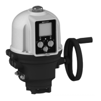
Do you have a question about the Bernard Controls EZ60 and is the answer not in the manual?
Guidance on wiring components, integrating thermal protector and torque limit switches, and performing initial electrical checks.
Instructions for adjusting mechanical stops and setting travel limit switches for proper actuator operation within 90° range.
Steps to set the potentiometer for accurate valve position feedback, covering both circuit board and support column mounted versions.
Details on connecting and setting up the TAM transmitter for linear 0/4 to 20 mA signal proportional to valve position.
Information on connecting switches for OPEN and CLOSED signalling, actuated by brown and grey cams.
Overview of MINIGAM+ controls for valve positioning, input signals, and dead band adjustment for accuracy.
Important considerations for electrical connections, signal cable separation, and shield connection for MINIGAM+.
How to set input-output signals and operating parameters using switches on the MINIGAM+ circuit board.
Procedure for adjusting mechanical stops and travel limit switches for MINIGAM+ actuators, ensuring correct valve travel.
Steps to set the closed (0%) and open (100%) positions for the remote position signal output on MINIGAM+.
Instructions on adjusting the dead band potentiometer to correct actuator 'hunting' and ensure stable positioning.
Details on connecting switches for OPEN and CLOSED signalling, managed by brown and grey cams.
Recommendation to supply the heating resistor upon actuator installation to prevent condensation.
Safety advice to replace covers immediately after start-up and ensure seals are clean and intact.
Table listing common problems, their causes, and corrective actions for actuator operation and control.
| Operating temperature | -20°C to +70°C |
|---|---|
| Type | Electric actuator |
| Power supply | 24 V AC/DC |
| Control type | On-Off / modulating |
| Voltage Range | 24 V AC/DC |
| Control Signal | 4-20mA |
| Communication | Modbus |
| Mounting | Direct mounting on |
| Protection class | IP67 / NEMA 4X |
| Protection Rating | IP67 / NEMA 4X |
