Do you have a question about the Bernard Controls ST INTELLI+ and is the answer not in the manual?
Device compliance with safety standards; installation by skilled and trained staff only.
Securing actuator to valve, cable gland orientation, and manual handling notes.
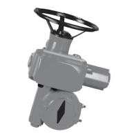
Operation of the automatic declutching handwheel and clutch button for manual control.
Wiring details, cable gland usage, and preliminary electrical checks for actuators.
Procedure for setting travel limit switches using cams on a cylindrical block.
Description of cams and their independent setting for open and close travel limits.
Steps to set travel limit switches for closed and open positions and perform checks.
Using the closed travel limit switch to shunt the opening torque limiter.
Information on factory calibrated torque limit system and troubleshooting.
Setting the proportional optical indicator by rotating the disc to align symbols.
Details on the signal feedback potentiometer and its mounting.
Delivers 0/4 to 20 mA signal proportional to valve position.
Power supply, load values, and wiring examples for the TAM transmitter.
How to invert the signal variation direction using jumpers on the board.
Procedure to adjust the 0/4mA and 20mA output values for the TAM transmitter.
Ensure protection covers are closed and dry to prevent water entry.
Actuators require no specific maintenance; guidelines for storage and lubrication.
| Brand | Bernard Controls |
|---|---|
| Model | ST INTELLI+ |
| Category | Controller |
| Language | English |