(Fig. 1)
(Fig. 2)
10 11
1 SAFETY INFORMATION
This device complies to current applicable safety standards.
Installation, maintenance and use of this apparatus by skilled and trained
staff only.
Please read carefully the whole document prior to mounting and starting-up.
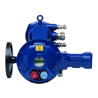
2 ASSEMBLY
Actuator should be secured directly to the valve using proper bolts
or via a proper interface.
After assembly, the actuator can operate in any position. However,
cable glands should not be oriented upwards (loss of water tightness)
and the motor will preferably not be positioned at the bottom (potential
internal condensation trap)
Note 1 : do not handle the actuator by handwheel, it could damage the
gears.
Note 2 : if the actuator was delivered mounted on the valve, the basic
settings should have been done. In this case, refer to § 3, 4,
10 and 11 only.
Note 3 : see §.11 for details on storage precaution prior to starting-up.
Note 4 : greasing of A form drive bush has to be done prior to mounting
actuator on valve.
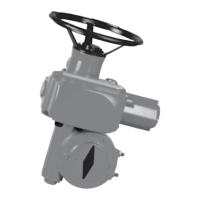
3 EMERGENCY HANDWHEEL AND DECLUTCH
All ST range actuators are provided with an automatical declutchling
handwheel, with motor drive priority. Operating direction is normally
indicate on the handwheel.
The ST6 actuator has a handwheel clutch button. In order to operate
manually the actuator, turn the arrow of the button in front of the trian-
gular sign (Fig. 1) on the housing (it could be necessary to turn the hand-
wheel of a few degrees to positionate the claws).
When the motor start, the button return automatically in its declutched
position.
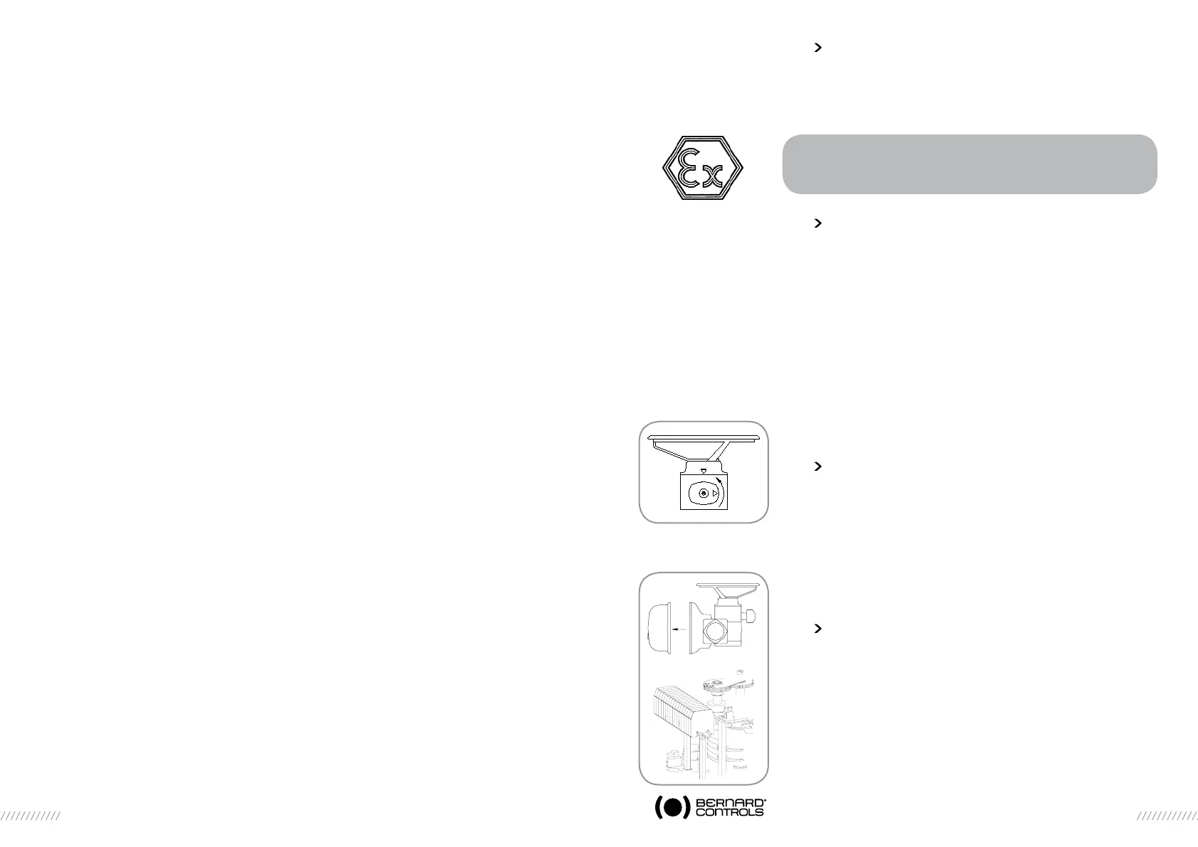
4 ELECTRICAL CONNECTIONS AND PRELIMINARY TESTS
If the actuator is equipped with INTEGRAL, MINIGRAL or MINIGAM
commands, please report to the specific documentation for wiring
details. Otherwise, all components of the actuator are wired to a common
terminal strip (Fig.2). Remove the cover and pass the cables through
the cable glands (M20). Refer to the standard wiring diagram on page
1 (or to the specific wiring diagram provided on request) for details
on the terminals numbering system. Both torque and travel limit switches
must be integrated into your control system (see wiring examples) in order
to prevent potential damage to the actuator or valve.
WARNING
For explosionproof actuators, please also read carefully
the special instructions NR1132 prior to mounting
and starting-up
Les servomoteurs doivent donc être stockés sous abri dans un endroit
propre et sec et protégé des changements successifs de température.
Eviter le stockage à même le sol.
Pour les motorisations équipées de résistance de chauffage, alimenter
celle-ci dans le cas de présence d’humidité (tension standard 230 volts,
sans précision particulière à la commande).
Vérifier que les bouchons plastique provisoires des entrées de câble
sont bien en place. En cas de présence d’humidité, remplacer ceux-ci par
des bouchons filetés métalliques.
S’assurer de l’étanchéité des couvercles des boîtiers renfermant les éléments
électriques.
Contrôle après stockage
a) Durée du stockage inférieure à 1 an :
- Contrôle visuel de l’équipement électrique.
- Actions manuelles sur les contacts, boutons, sélecteurs, etc... pour
en contrôler le bon fonctionnement mécanique. Procéder à quelques
manoeuvres manuelles.
- Vérifier la bonne consistance de la graisse.
b) Durée du stockage supérieure à 1 an :
- Le stockage à long terme entraîne un changement dans la consis-
tance de la graisse. En faible épaisseur sur les axes ou tourillons,
elle se dessèche. Il est donc nécessaire de procéder au démontage
et au dégraissage de toute la partie mécanique du servomoteur et
remonter celui-ci avec de la graisse neuve.
- Contrôle visuel de l’équipement électrique.
- Actions manuelles sur les contacts, boutons, sélecteurs, etc... pour en
contrôler leur bon fonctionnement mécanique.
Graissage
SHELL TIVELA COMPOUD (ST6 : 2kg / ST14 : 3kg / ST30 : 3,5kg / ST70 : 4,5kg).