EasyManua.ls Logo

Bernard Controls SQX Series - User Manual

Bernard Controls SQX Series
79 pages
Print Icon
To Next Page IconTo Next Page
Loading...
INSTRUCTIONS FOR START-UP
SQX & STX INTELLI+ RANGES
MANUEL DE MISE EN SERVICE
GAMMES SQX & STX INTELLI+
(ATEX & IECEx)
NR 1179_rev.06
Art : 5100109
SQX
STX
Gamme
Range

Table of Contents

Other manuals for Bernard Controls SQX Series

Questions and Answers

  • C
    Craig MillerAug 19, 2025
    What to do if the motor thermal switch trips in Bernard Controls Measuring Instruments?
    • R
      Robert VargasSep 12, 2025
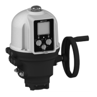
      If a black square appears at the bottom center of the display, it indicates an alarm. To check if it's a motor overheating alarm, go to menu / check / alarms. The actuator will become available again once the motor cools down.
  • L
    Larry SmithAug 21, 2025
    What to do if the display in menu mode in Bernard Controls Measuring Instruments?
    • A
      Angela FordAug 21, 2025
      If the device is stuck in menu mode, set the local / remote selector to off and then back to local. This should switch the display to command mode, showing the position.
  • E
    ehumphreyAug 23, 2025
    What to do if local command override or ESD command active in Bernard Controls Measuring Instruments?
    • R
      Richard MitchellAug 23, 2025
      Check Aux. command 1 or 2 options in the command menu to see whether a command override or emergency command has been set up. Also, check the status (open/closed) of the contact used to perform this remote command and verify the connection on the client terminal to ensure it corresponds to a command override or emergency command.
  • B
    Breanna RodriguezAug 26, 2025
    What to do if local command override is active in Bernard Controls Measuring Instruments?
    • W
      whendersonAug 26, 2025
      Check Aux. command 1 or 2 options in the command menu to see whether a command override has been set up and check the status (open/closed) of the contact used to perform this remote command.
  • O
    otaylorAug 27, 2025
    What to do if changes cannot be made in the check menu of Bernard Controls Measuring Instruments?
    • H
      Heather CunninghamAug 28, 2025
      If you can't make changes in the check menu, go to the change menu instead. Some settings are designed to be view-only in the check menu.
  • E
    ericsilvaAug 30, 2025
    What to do if the motor wiring changed and motor rotates in reverse direction in Bernard Controls Measuring Instruments?
    • I
      iaustinAug 30, 2025
      When replacing the motor, adhere to the wiring tags. If unsure, verify the motor rotates correctly. To reverse the motor's direction, switch wires 2 and 3 on the motor terminal strip inside the control box.
  • K
    kenneth56Sep 1, 2025
    What to do if the selector is on remote or off, or local command override is active in Bernard Controls Measuring Instruments?
    • C
      craig85Sep 1, 2025
      The menu can only be accessed via the selectors in local mode, i.e. with the selector on local and no override on local control.
  • B
    Brett HallSep 3, 2025
    What to do if the local / remote selector on remote or off (stop) in Bernard Controls Measuring Instruments?
    • H
      Holly AcostaSep 3, 2025
      If the local / remote selector is set to remote or off (stop), switch it to the local position.
  • E
    erin91Sep 5, 2025
    What to do if voltage control is not adapted to input in Bernard Controls Measuring Instruments?
    • C
      Christine GraySep 5, 2025
      Check voltage control connections: use terminal 5 for 10 - 55 volts and terminal 4 for 55 to 250 volts.
  • C
    cardenasvanessaSep 7, 2025
    What to do if changes cannot be saved in Bernard Controls Measuring Instruments?
    • V
      Victoria GloverSep 7, 2025
      After making changes, navigate back through the menus using 'return' and 'OK' until the display shows '(change ok?)'. Turn to 'OK' to confirm and save the changes.

Summary

1 > SAFETY INFORMATION

1.1 > MARKING

Details ATEX, IECEx, and IEx certification markings for actuators.

1.2 > INSTALLATION AREA

1.3 > CAUTIONS FOR ELECTRICAL CONNECTION

Provides safety precautions for opening covers and electrical connection procedures.

1.4 > OPERATION

1.5 > MAINTENANCE

Guidelines for regular checks, lubrication, and repair of actuators.

1.6 > ELECTRICAL AND TEMPERATURE PARAMETERS

1.7 > SPECIAL OPERATION CONDITIONS INCLUDING UNCORRECT PRACTICES

Discusses duty cycles and cover opening precautions for safe operation.

1.8 > LIST OF APPLICABLE STANDARDS

Lists relevant IEC and EN standards for explosion-proof equipment.

2 > PRODUCT OVERVIEW

Manual override

Explains the handwheel function for manual control with automatic clutch.

3 > STORAGE

Inspection following storage

Procedures for inspecting actuators after short-term or long-term storage.

4 > ACTUATOR ON VALVE ASSEMBLY

5 > ELECTRICAL CONNECTION

6 > ACTUATOR ON VALVE SETTING INTRODUCTION

7 > REMOTE CONTROL

7.1 > DRY CONTACT CONTROL

Configuration for dry contact remote control with jumper settings.

7.2 > VOLTAGE CONTROL

Using AC or DC voltage for remote control and voltage range cautions.

8 > LOCAL CONTROL USING BUTTONS AND DISPLAY

Symbols that may appear on the display

Explains various icons and their meanings displayed on the actuator.

9 > NAVIGATING IN THE MENUS

9.1 > SELECTORS

Identifies the functions of the blue and red selector knobs for menu navigation.

9.2 > MAIN MENU

Accessing and navigating the main menu options.

9.3 > SELECT A MENU OR AN OPTION

Step-by-step guide to selecting menus and options.

9.4 > SAVING THE CHANGES

Procedure for saving modifications made in the CHANGE menu.

9.5 > EXITING THE MENU AT ANY TIMES

How to exit the menu system using the red selector.

9.6 > MAIN MENU DESCRIPTION

Detailed description of each option within the main menu.

10 > SELECTING THE DISPLAY LANGUAGE

11 > PASSWORD

12 > CHECK MENU FLOWCHART

13 > SET UP AND CHANGE MENU FLOWCHART

14 > ADJUSTING AN ACTUACTOR ON A VALVE

14.1 > MANUAL SET UP

Detailed steps for manual setup of valve positions and closing mode.

14.2 > AUTOMATIC SET UP

15 > POSITION SIGNAL AND POSITIONER

How actuators handle position signals and function as positioners.

16 > COMMANDS

16.1 > REMOTE CONTROL VIA SINGLE CONTACT

Configuration for controlling the actuator with a single external contact.

16.2 > AUXILIARY REMOTE CONTROLS

Using additional remote commands for specific functions.

Description of the commands

Detailed explanation of various auxiliary command functions.

16.3 > LOCAL COMMANDS

16.4 > LOCAL STOP

Disabling the local stop function when set to remote control.

16.5 > REMOTE STOP

Configuring remote stop functionality similar to open/close commands.

16.6 > OPEN OR CLOSE PRIORITY

16.7 > ESD IN DEGRADED MODE

Enabling fault-tolerant operation for emergency shutdown commands.

16.8 > PARTIAL STROKE

Performing periodic functional tests on motorized valves.

17 > LOCAL COMMUNICATION WITH PC

17.1 > LOCAL INFRARED COMMUNICATION

Using an infrared kit for communication with laptops.

17.2 > LOCAL BLUETOOTH COMMUNICATION (OPTION)

Wireless communication via Bluetooth for setup and control.

18 > SETTING AND VIEWING TORQUE VALUES

18.1 > CLOSING TYPE

Selecting whether the valve closes based on position or torque.

18.2 > TORQUE SETTING

Adjusting torque percentage settings for closing and opening.

Description of torque limit system

18.3 > TORQUE READINGS AND COMPARISON WITH ORIGINAL TORQUE VALUES

Measuring and comparing current torque values with historical data.

19 > CUSTOMIZING STATUS AND CONTROL INDICATIONS

19.1 > LOCAL INDICATION

Customizing the local display, including invert, torque, and LED color settings.

19.2 > REMOTE INDICATIONS

Liste

List of available options for configuring remote indication relays.

20 > CUSTOMIZING FAULT RELAY

21 > TIMING MOVEMENT TRAVEL

22 > VIEWING ACTUATOR HISTORY

22.1 > ACTIVITY

Viewing total starts, running time, and handwheel usage.

22.2 > ALARMS

Displaying and interpreting active alarms to diagnose malfunctions.

23 > ACCESSING DATA SHEET

Characteristics menu details

Detailed explanations of various actuator characteristics.

24 > CREATING OR CHANGING PASSWORD

25 > USING ANALOGUE POSITION SIGNAL (DEPENDING ON MODEL)

26 > USE AS A POSITIONER WITH AN ANALOGUE CONTROL SIGNAL (DEPENDING ON MODEL)

26.1 > INPUT SIGNAL

Selecting and configuring input signal types and directions.

26.2 > SETTING OF DEADBAND VALUE

26.3 > FAIL-SAFE POSITION

Setting a fail-safe position for when the control signal is lost.

26.4 > PROPORTIONAL PULSE MODE

Using proportional pulse mode to improve positioning with inertia.

27 > USING FIELDBUS CONTROL (DEPENDING ON MODEL)

28 > USING IN CASE OF POWER SUPPLY LOST (WITH BATTERY DEPENDING ON MODEL)

29 > FUSE PROTECTION

30 > USING IN SEPARATED BOX

31 > MAINTENANCE

32 > TROUBLESHOOTING

32.1 > INTELLI+

Troubleshooting guide for INTELLI+ specific issues.

32.2 > POSITIONER OPTION

Bernard Controls SQX Series Specifications

General IconGeneral
BrandBernard Controls
ModelSQX Series
CategoryController
LanguageEnglish

Related product manuals