12
8 LOCAL CONTROL USING BUTTONS AND DISPLAY
The local control facility provides a means of operating
the actuator electrically without using an external control
circuit. There is a switch for selecting remote control,
local control or disabled (off). The local open/close switch
is used to operate the actuator in the direction required.
Movement can be halted locally by turning the local/
remote selector switch briefly to the STOP position.
The display shows the position of the valve as a percentage
of opening when it is partially open.
The display shows “Closed” when the valve is closed.
The display shows “Open” when the valve is open.
The display is factory set to show the instantaneous torque
as a percentage of the maximum actuator torque value
< 10% indicates the minimum torque value.
Symbols that may appear on the display:
A remote command inhibits the local controls (see § 16.2)
The actuator receives an emergency shutdown command (see § 16.2)
An infrared link is detected (see § 17.1)
A bluetooth link is detected (see § 17.2)
indicates the presence of an alarm. (see §22.2 for the types of alarm)
In case of a battery option, the icon blinks if the battery voltage is low.
This icon indicates that the control is proportional (4-20 mA i.e) and the value
of the input signal (setpoint) is indicated in %. Blinking if 4-20 mA signal is missing.
The BUS marker indicates there is a bus communication card. The marker is followed
by a square that shows you the communication status (see specific documentation
of the installed bus).
1 and 2 indicate the presence of a redundant communication card (2 communication
channels). The number is followed by a square indicating the status of each communi-
cations channel (see the specific doc. of the installed bus).
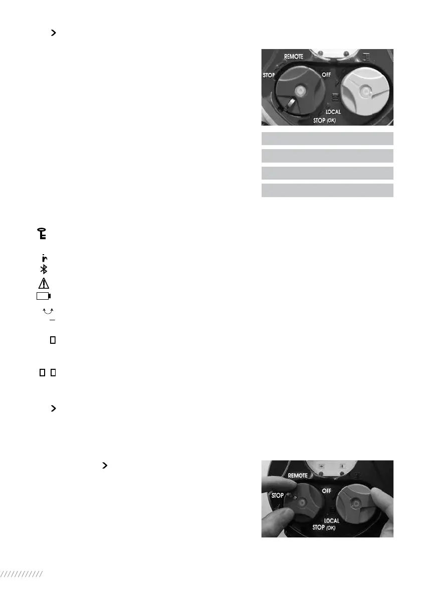
9 NAVIGATING IN THE MENUS
The selector switches used for operating the actuator’s electrical motor drive is also used to navi-
gate into the INTELLI+ menus and thus to have access to the settings.
9.1 SELECTORS
Blue selector (on the right)
- choice selection
Red selector (on the left)
- selector on OK: choice validation
- selector on OFF: exit the menu at any time
20% Open
Closed
Open
Torque 60%
BUS
0%
1 2
 Loading...