LaserSpeed 8000/9000 I/O Module Instruction Handbook
Installation
Part No. 93342 / Drawing No. 0921-01516 Page 17 of 84 Revision E (Dec 2013)
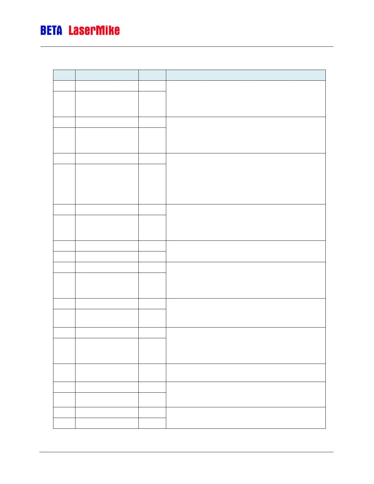
Pin Assignment for System Status
Contact Closure Output indicating the Material Present
state.
Closed = Material is Present
Open = Material is Not Present
Contact Closure Output indicating when the LaserSpeed
gauge is making valid measurements
Closed = LaserSpeed gauge is Measuring
Open = LaserSpeed gauge is Not Measuring
Contact Closure Output indicating if the system is ready
to measure. This output is closed when the Laser is ON,
the Shutter is Open, and the Laser is at the correct
temperature.
Closed = System is Ready to Measure
Open = System is Not Ready to Measure
Contact Closure Output indicating if the Laser Power is
on.
Closed = Laser is ON
Open = Laser is OFF
Reserved Contact Closure Output
Do Not Connect
Contact Closure Output indicating if the Laser is at the
correct temperature.
Closed = Laser Temperature is Ok
Open = Laser Temperature is not within tolerance
Laser is Operational: Shutter Open + Laser Power
Closed = Laser is Operational (Laser emission)
Open = Laser is not Operational (no Laser emission)
Contact Closure Output indicating if the I/O Module is
communicating with the LaserSpeed gauge.
Closed = Communication Ok
Open = Not Communicating
+5VDC Output for connection to interlock signals when
wiring as contact closure Inputs.
Laser Interlock input to LS9000/LS8000. See
connection diagram for wiring instructions. See also note
at end of table.