23
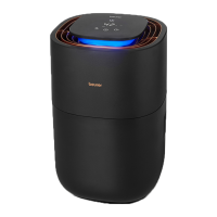
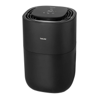
5. DEVICE DESCRIPTION
The associated drawings are shown on page 3.
Air humidifi er Control panel
1
Control panel
2
LED light ring
3
Air outlet
4
Motor unit
5
Filter
6
Water level sensor
7
“Max.” mark
8
Filter holder
9
Water tank
10
Air inlet
11
ON/OFF button
12
Display
(shows current relative humidity, fan speed and timer duration)
13
Target humidity indicator
14
Target humidity button
15
Timer button
16
Fan speed button
17
NIGHT indicator
(lights up when NIGHT mode is active)
18
AUTO indicator
(lights up when AUTO mode is active)
19
Filter drying indicator
(lights up when fi lter drying function is active)
20
Filter change indicator
(lights up when fi lter change is necessary)
21
Water tank indicator
(lights up when the water tank is empty/needs to be refi lled)
6. INITIAL USE
1. Open the cardboard packaging.
2. Remove the device from the top of the box without opening the fi lm bag.
3. Remove all fi lms and adhesive strips. Remove the fi lter
5
from the device (see section “8.3 Changing
the fi lter”) and take it out of the plastic fi lm. Then re-insert the fi lter
5
into the device.
4. Check the device, mains plug and cable for damage.
7. USAGE
7.1 Starting use
Step 1: Position the air humidifi er
1.
Place the air humidifi er on a stable, horizontal and level surface to
prevent vibrations and noise. Never move the air humidifi er during use.
2. Set up the air humidifi er in such a way that provides 30 cm clearance
on all sides.
3. Make sure that the air inlet
10
and air outlet
3
are never blocked.
 Loading...