34
1.3 Addressing the Microphone Units
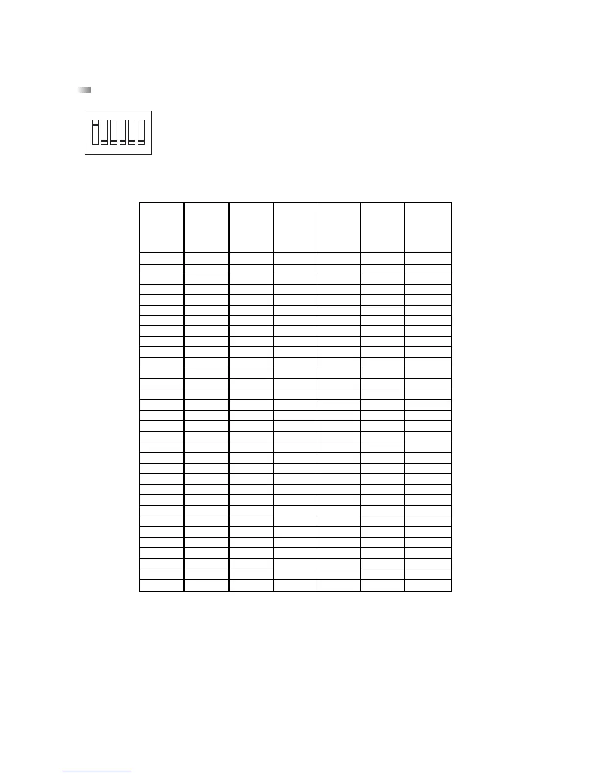
Before the system is set up, the microphone units have to be addressed via DIP-switches on the bottom according to the
following table.
1 = DIP-switch in ON position = switched on
0 = DIP-switch in a number position = switched off
The DIP-switch 6 has no function.
Note:
At the factory the microphone unit 1 has been configured as a chairman microphone unit. Using the MCS-Editor another microphone
unit can be chosen as a chairman microphone unit.
Furthermore, make sure that there are not two microphone units having the same address within the same line. For assistance use
the MCS-Editor (refer to chapter 6.8 “Status Check”).
Important:
The chairman microphone unit has to be defined again with the MCS-Editor, when there is a reset necessary (user or manufacturer
specific).