MANUAL INSTALLATION
Version: 1.0 (22-09-2005) 17
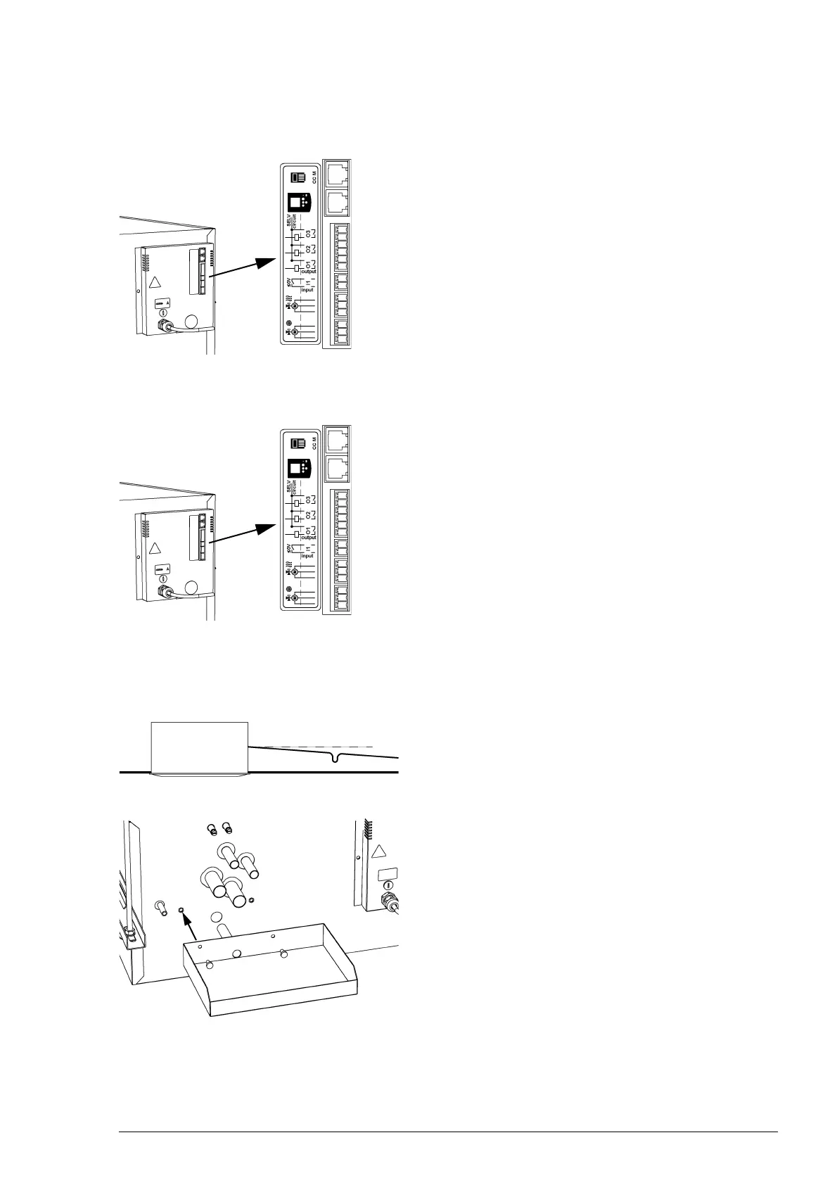
Connecting CH and CW separately
1. Connect the CH signal cable to output O1 1.
2. Connect the cold water machine signal cable to
output
O2 2.
3. Set function 91 (output O1 function) to value 55 (heating
demand).
4. Set function 91.5 to value 0 (make contact ).
5. Set function 92 (output O2 function) to value 56 (cooling
demand).
6. Set function 92.5 to value 0 (make contact ).
Connecting CH and CW together
1. Connect the signal cable of the change-over system to out-
put O1 1.
2. Set function 91 (output O1 function) to value 57.
3. Set function 91.5 to value 0 (make contact ).
If the unit switches from heating mode to cooling mode, a
signal is sent to the output.
2.7 Connecting the condensate discharge (CC C)
The units with cooling come standard with a condensate
draining pump. The condensate is drained from the unit
through a flexible hose.
1. Install a sewer connection incl. stink trap for the discharge
of condensate.
2. Connect the discharge hose 1 to the drain pipe.
In doing so, pay attention to this:
- For proper condensate discharge, the drain pipe must
be sloping (>2%).
- Avoid kinks in the discharge hose.
- Above the ceiling, the discharge hose must be insulated.
3. Mount the external drip tray 2 using the supplied
screws
3.
1
2
1
>2%
1
2
3
3