10
RP 14/15 M30x2 41 150
RP 30 M40x2 50 350
RP 60 M45x2 55 500
RP 120 M50x2 60 800
RP 14/15 17 41
RP 30 17 50
RP 60 17 55
RP 120 17 60
RP 15-MSJ/MHW 24 41
RP 30-MSJ/MHW 32 50
RP 60-MSJ/MHW 36 55
RP 120-MSJ/MHW 36 60
RPS SPRING RETURN PNEUMATIC ACTUATOR
INSTALLATION, OPERATION AND MAINTENANCE MANUAL
3.2 Residual risks
WARNING
The actuator has parts under pressure. Use the
due caution.
Use individual protections provided for by the laws
and provisions in force.
3.3 Operations
The operations are carried out sending the
proper signal through the control system in
compliance with customer specifications.
Please refer to the functional diagram and
specific documentation supplied.
3.4 Calibration of the angular stroke
It is important that the mechanical stops of the
actuator (and not those of the valve) stop the
angular stroke at both extreme valve position
(fully open and fully closed), except when this
is required by the valve operation (e.g. metal
seated butterfly valves).
The setting of the angular stroke is performed
by adjusting the travel stop screws of the
cylinder end flange and of the housing wall.
The setting of the open valve position is
performed by adjusting the travel stop screw
on the left side of the actuator (screwed in the
housing wall for spring to close actuators or
in the cylinder end flange for spring to open
actuators).
The setting of the closed valve position is
performed by adjusting the travel stop screw
on the right side of the actuator (screwed in
the cylinder end flange for spring to close
actuators or in the housing wall for spring to
open actuators).
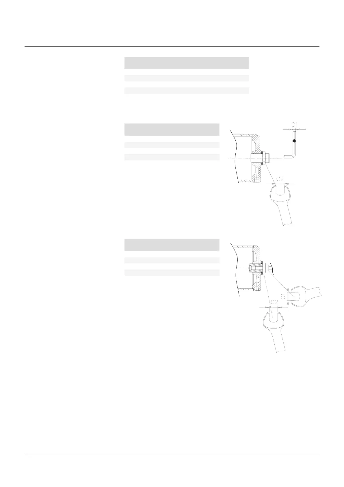
For the adjustment of the travel stop screws
proceed as follows (see figures 9A, 9B):
1. Loosen the lock nut with wrench C2.
2. If the actuator angular stroke is stopped
before reaching the end position (fully open
or closed), unscrew with wrench C1 the
travel stop screw by turning it anticlockwise,
until the valve reaches the right position.
When unscrewing the travel stop screw,
keep the lock nut still with a wrench so
that the sealing washer does not withdraw
together with the travel stop screw.
3. Tighten the lock nut (refer to torque table to
avoid accidental unscrewing of the lock nut).
4. If the actuator angular stroke is stopped
beyond the end position (fully open or closed
valve), screw the stop screw by turning it
clockwise until the valve reaches the right
position.
5. Tighten the lock nut (refer to torque table to
avoid accidental unscrewing of the lock nut).
Actuator model Thread
Wrench C2
(mm)
Torque
(Nm)
Actuator model
Wrench C1
(mm)
Wrench C2
(mm)
Actuator model
Wrench C1
(mm)
Wrench C2
(mm)
FIGURE 9A, 9B
Without jackscrew manual override
With jackscrew manual override MSJ or
handwheel manual override MHW