4
3A
3B
RPS SPRING RETURN PNEUMATIC ACTUATOR
INSTALLATION, OPERATION AND MAINTENANCE MANUAL
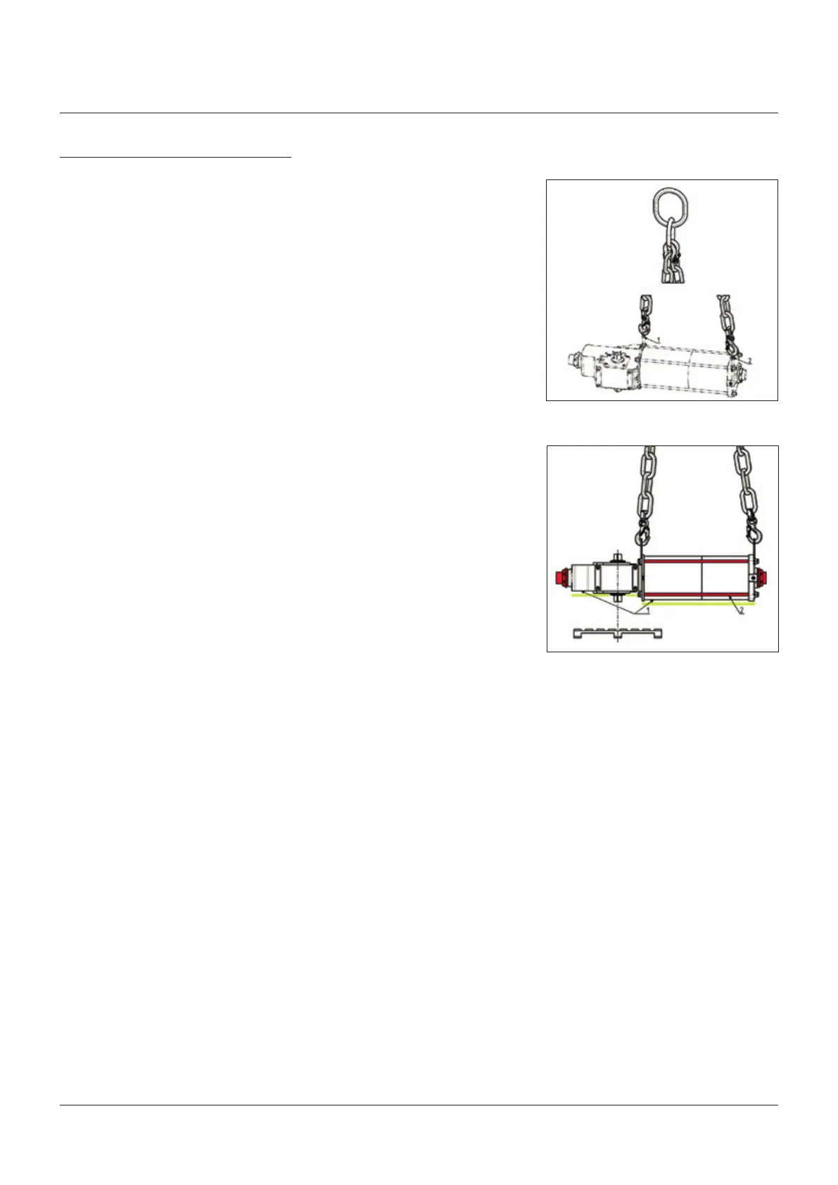
2.2 Actuator handling
A. Valve stem with vertical axis
IMPORTANT
The lifting and handling should be made by
qualified staff and in compliance with the laws and
provisions in force.
WARNING
The fastening points are appropriate for the lifting
of the actuator alone and not for the valve and
actuator assembly.
Avoid that during the handling, the actuator
passes above the staff.
The actuator should be handled with appropriate
lifting means. The weight of the actuator is
reported on the delivery bill.
For a correct lifting procedure, please refer to
figure 3A, 3B.
A. Valve stem with horizontal axis
The actuator can also be lifted to assemble
directly onto the valve with stem with horizontal
axis. To make this operation easier, Biffi
suggest to move the lifting eyelet from its
standard position, and place it in the suggested
position, see figure 4.
2 INSTALLATION
2.1 Checks upon actuator receipt
• Check that the model, the serial number of
the actuator and the technical data reported
on the identification plate correspond with
those of order confirmation (section 1.2).
• Check that the actuator is equipped with the
fittings as provided for by order confirmation.
• Check that the actuator was not damaged
during transportation: if necessary renovate
the painting according to the specification
reported on the order confirmation.
• If the actuator is received already assembled
with the valve, its settings have already been
made at the factory.
If the actuator is delivered separately
from the valve, it is necessary to check,
and, if required, to adjust, the settings of
the mechanical stops (section 3.4) and of
microswitches (if any) (section 3.5).
FIGURE 3A, 3B
Lifting points for RPS actuators
1 = Points of support
2 = Do not lay the actuator on tie-rods
WARNING
Do not lay the actuator on accessories (manual
hand pump, manual jackscrew, pneumatic control
system etc.)
1, 2 = Lifting eyelets