6
Y
A
A
K
K
B
B
L
J
J
G
D
ØM
ØF
ØE
ØH
ØC ØC
ØE
X
RP 14/15 49.5 49.5 M8 10 16 21 23 66 30 3 140 40 M5
RP 30 72.1 72.1 M10 12 22 29 25 92 32 3 164 50 M5
RP 60 88.4 88.4 M12 15 28 37 34 112 42 3 204 60 M5
RP 120 99.0 99.0 M16 23 37 49 45 132 55 3 270 75 M8
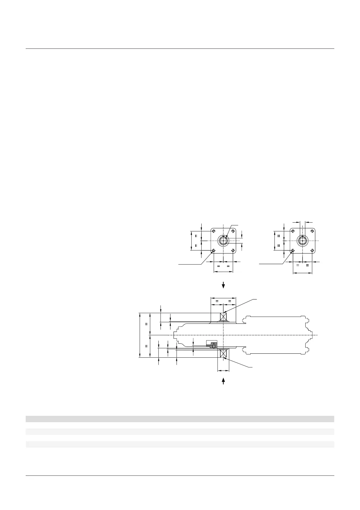
2.4 Actuator assembly on the valve
2.4.1 Types of assembly
For coupling to the valve, the housing is
provided with a flange with threaded holes
according to Biffi standard tables (see figure 5).
The number, dimensions and diameter of the
holes are made in accordance with ISO 5211.
The actuator is provided with a spool piece
and a stem extension for coupling to the valve.
The assembly position of the actuator, with
reference to the valve, must comply with the
plant requirements (cylinder axis parallel or
perpendicular to the pipeline axis).
IMPORTANT
To fix the actuator to the valve flange must be
used the stud bolts and nuts supplied by Biffi!
In case the actuator is supplied without stud bolts
and nuts the following materials must be used as
a minimum:
ASTM A 193 grade L7 for stud bolts
ASTM A 194 grade 4 for nuts
2.3 Storage
If the actuator needs storage, before
installation follow these steps:
• Place it on a wood surface in order not to
deteriorate the area of valve coupling.
• Make sure that plastic plugs are present on
the pneumatic and electrical connections
(if present).
• Check that the cover of the control group and
of the limit switch box (if any) are properly
closed.
If the storage is long-term or outdoor:
• Keep the actuator protected from direct
weather conditions.
• Replace plastic plugs of pneumatic and
electrical connections (if any) with metal
plugs that guarantee perfect tightness.
• Coat with oil, grease or protection disc, the
valve coupling area.
• Periodically operate the actuator (section 3.3).
COUPLING DIMENSIONS (mm)
Actuator model A ± 0.2 B ± 0.2 ØC D ØE ØF G ØH K J L ØM ØN
NOTE
Both the actuator flanges can be used for the coupling to the valve or the mounting of ancillary equipments (positoner, limit switch box, etc. )
View from X View from Y
№4 threaded holes №4 threaded holes
Threaded hole ØN
Threaded hole ØN
FIGURE 5
RPS SPRING RETURN PNEUMATIC ACTUATOR
INSTALLATION, OPERATION AND MAINTENANCE MANUAL