REV A 4-8 121536
Air creates inefficiency because its compression and
expansion rate is higher than that of the oil approved for use
in hydrostatic drive systems.
These purge procedures should be implemented any time a
hydrostatic system has been opened to facilitate mainte-
nance or the oil has been changed.
The resulting symptoms in hydrostatic systems may be:
1. Noisy operation.
2. Lack of power or drive after short term operation.
3. High operation temperature and excessive expansion
of oil.
Before starting, make sure the transaxle is at the proper oil
level. If it is not, fill to the specifications outlined in this man-
ual.
The following procedures are best performed with the vehi-
cle drive wheels off the ground. Then repeated under normal
operating conditions. If this is not possible, then the proce-
dure should be performed in an open area free of any objects
or bystanders.
1. Raise and block the mower up so the drive wheels are
off of the floor.
2. Position the control lever in the neutral position. Dis-
engage the deck clutch switch. Figure 4-7
3. With the bypass valve open and the engine running,
slowly move the directional control in both forward
and reverse directions (5 or 6 times). Figure 4-19
4. With the bypass valve closed and the engine running,
slowly move the control lever in both forward and
reverse directions (5 or 6 times). Check the oil level,
and add oil as required after stopping the engine.
5. It may be necessary to repeat Steps 3 and 4 until all
the air is completely purged from the system. When
the transaxle operates at normal noise levels and
moves smoothly forward and reverse at normal
speeds, then the transaxle is considered purged.
This procedure will require that the unit be raised
to allow the drive wheel to rotate.
• Block the mower up off of the ground using
only appropriate vehicle stands (minimum
weight rating of 2000 pounds). Use in pairs
only. Follow the instructions supplied with
the vehicle stands.
• Do not allow the wheels to come in contact
with the floor or any object that would permit
the unit to propel itself.
• To prevent injury stay clear and exercise cau-
tion when rotating the wheels.
WARNING
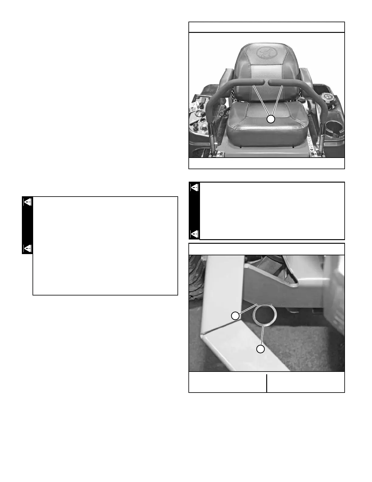
Shown with steering control levers in the neutral position
A. Steering control lever
Figure 4-18
Allow engine exhaust manifold to cool before engag-
ing or disengaging the bypass valves. The bypass
valve rods are located close to the exhaust system.
Bypass valve rod show in operating position
A. Bypass valve rod (left
rod shown)
B. Slot
Figure 4-19
A
WARNING
B
A
 Loading...