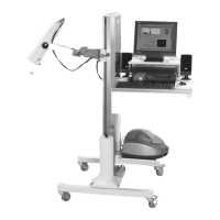
24. Remove the tube assembly and base from its packaging. Notice that a grounding strap is wrapped
around the base and tube assembly. This is necessary to properly ground the detector shroud to the
base and stabilize the count rate. Remove the red protective cap from the detector and carefully
insert the detector and base assembly into the cone shaped collar. Slide the detector downward until
the entire assembly is inserted. At this point, the detector cables should be flush with the top of the
collimator. Tighten the set screw to secure the detector in place.
NOTE: Do not force the assembly into position as it is possible to dent the shroud and damage the detector. If
the assembly will not slide easily into place, check to make sure the set screw has been sufficiently loosened.
25. Route the detector cables between the collimator and the uptake arm collimator yoke. Loosen the
collimator tilt locking knob and tilt the collimator so that the detector cables are in the furthest
position possible from the uptake stand vertical column (be sure to extend the collimator arm fully).
26. Insert the larger (MHV) detector cable connector through the large shelf back cable hole (alongside
the vertical column). You can now push the smaller (BNC) detector cable connector through the
same hole. Pull both cables out through the front of the MCA shelf and allow them to hang free.
27. Using a straight screwdriver, remove the wire wrap from the underside of the collimator arm. Place
the wire wrap around both detector cables and reinstall to the collimator arm. Before securing the
wire wrap screw, set the cables so that there is a little slack leading to the detector.
28. Remove the CPU from its packaging and place it on top of the large shelf. Make sure it faces the
front of the stand where the operator will be working.
29. Slide the CPU toward the back of the large shelf. Place the keyboard and trackball mouse on the
shelf in front of the CPU. The keyboard should be to the left of the trackball.
30. Run the free end of the keyboard cable along the side of the CPU and plug it into the keyboard port
at the back of the CPU.
31. To install the trackball, attach one end of the trackball cable to rear of the trackball. Run the opposite
end of the cable inside the CPU hold-down and plug it into mouse port on the rear of the CPU.
32. Take the CPU bracket that was removed in step #3 and position it over the CPU. The bracket lip
with the slotted holes should face towards the front of the CPU. With a Phillips screwdriver, reinstall
the six screws that secure the bracket to the large shelf. The keyboard cable should be on the inside
of the bracket so it is under the CPU.
33. Remove the monitor from its packaging and place it on top of the CPU bracket so that the monitor’s
swivel base is centered on the bracket.
34. Swivel the monitor 45 degrees and hook the front of the monitor bracket to the CPU bracket. With a
Phillips screwdriver and single screw, secure the back end of the monitor bracket to the CPU
bracket. Repeat this procedure to secure the opposite monitor bracket.
35. Run the monitor signal cable (one end fixed to the back of the monitor) into the monitor port at the
back of the CPU (an adapter may be required).
36. Plug the monitor power pack into the powerstrip. Run the other end of the power pack cable up the
right side hole and out the side of the stand. Now plug it into the monitor.
37. Take the female end of another power cord and plug it into the back of the CPU. Route the male end
of the cord through the large shelf side cable hole and down through the MCA shelf cable hole. Plug
the power cord into the power strip.
CONTENTS
2-5 SETUP INSTRUCTIONS