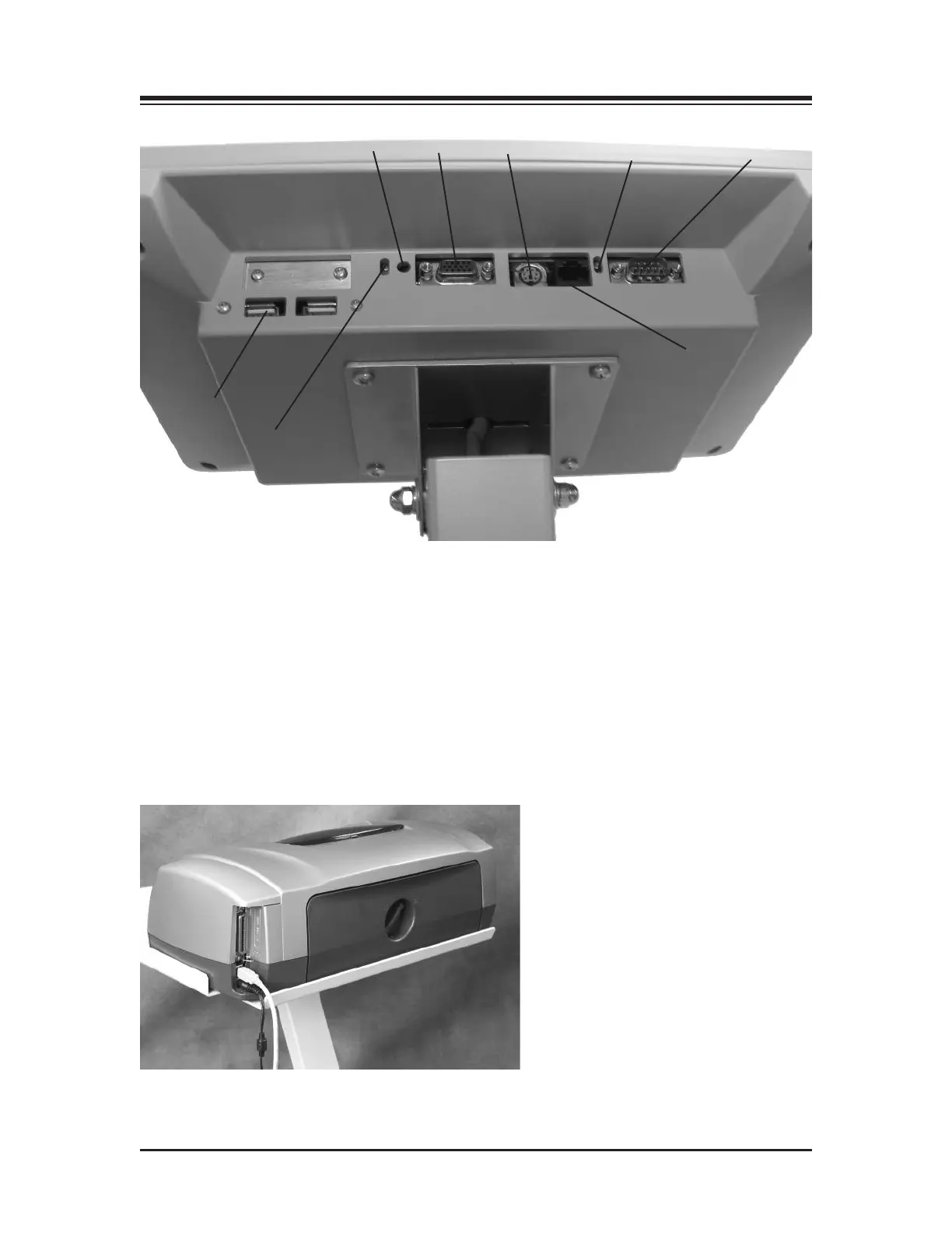
Figure 3.1. The printer power cable should be plugged into the AC receptacle on the rear base of the
display support post. The printer USB cable should be plugged into the USB port on back of the display.
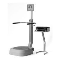
1. Reset Button
2. Remote CRT Monitor Connector
3. PS 2 Connector
4. Ethernet activity lights. Green indicates connectivity. Yellow indicates activity.
5. Auxiliary Com Port (Serial Port)
6. Ethernet Connector (RJ 45)
7. PCB activity lights. Green indicates compact flash activity. Yellow indicates power on.
8. USB Connectors (suggested to use one of these for printers)
Figure 3.2. Connect the power cable and USB cable to the rear of the printer.
CONTENTS
ASSEMBLY & INSTALLATION — 3-2 —
1
2
3
4
5
6
7
8