Motherboard Manual
14
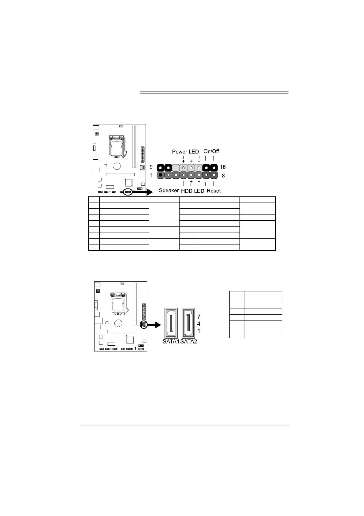
PANEL1: Front Panel Header
This 16-pin header includes Power-on, Reset, HDD LED, Power LED, and speaker
connection. It allows user to connect the PC case’s front panel switch functions.
Pin Assignment Function Pin Assignment Function
1 +5V 9 N/A
2 N/A 10 N/A
N/A
3 N/A 11 N/A N/A
4 Speaker
Speaker
Connector
12 Power LED (+)
5 HDD LED (+) 13 Power LED (+)
6 HDD LED (-)
Hard drive
LED
14 Power LED (-)
Power LED
7 Ground 15 Power button
8 Reset control
Reset button
16 Ground
Power-on button
SATA1~SATA2: Serial ATA 3.0 Connectors
These connectors connect to SATA hard disk drives via SATA cables. It satisfies
the SATA 3.0 specification and with transfer rate of 6.0Gb/s.
Pin Assignment
1 Ground
2 TX+
3 TX-
4 Ground
5 RX-
6 RX+
7 Ground
 Loading...