P4M800-M7 & P4M800-M7 A
15
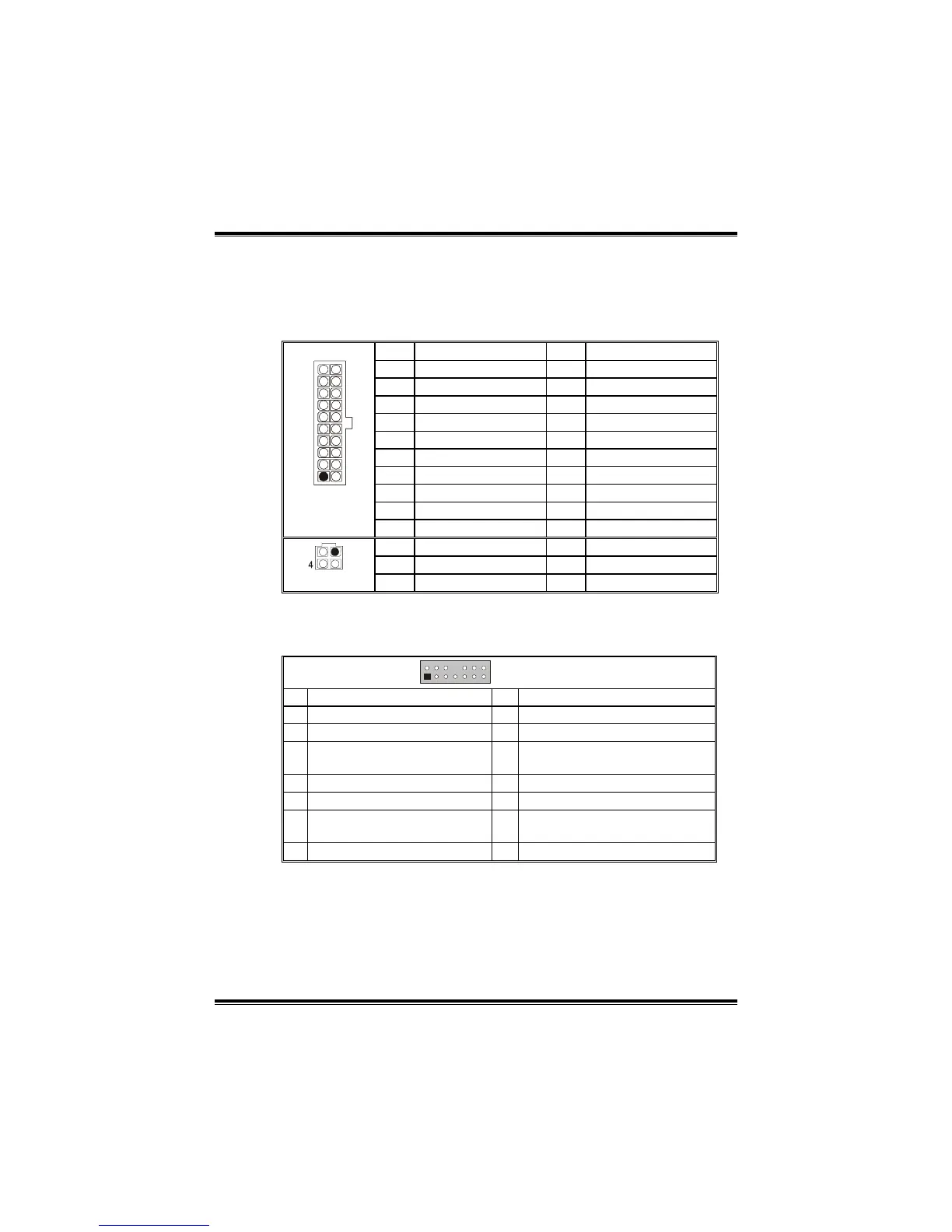
JATXPWR1/PATXPWR2: Power Connectors
JATXPWR1: This connector allows user to connect with 20-pin power
connector on the ATX power supply.
JATXPWR2: By connecting this connector, it will provide +12V to CPU
power circuit.
Pin Assignment Pin Assignment
1 +3.3V 11 +3.3V
2 +3.3V 12 -12V
3 Ground 13 Ground
4 +5V 14 PS_ON
5 Ground 15 Ground
6 +5V 16 Ground
7 Ground 17 Ground
8 PW_ON 18 -5V
9 Standby Voltage +5V 19 +5V
20
11
10
1
JATXPWR1
10 +12V 20 +5V
Pin Assignment Pin Assignment
1 +12V 3 Ground
1
2
3
JATXPWR2
2 +12v 4 Ground
JAUDIO1: Front Panel Audio Header
This header allows user to connect the front audio out put cable with the
PC front panel. It will disable the output on back panel audio connectors.
1
2
13
14
JAUDIO1
Pin Assignment Pin Assignment
1 Mic in/center 2 Ground
3 Mic power/Bass 4 Audio power
5
Right line out/Speaker out
Right
6 Right line out/Speaker out Right
7 Reserved 8 Key
9 Left line out/Speaker out Left 10 Left line out/Speaker out Left
11
Right line in/Rear speaker
Right
12 Right line in/Rear speaker Right
13 Left line in/Rear speaker Left 14 Left line in/Rear speaker Left
 Loading...