P4M800-M7 & P4M800-M7 A
14
CHAPTER 3: HEADERS & JUMPERS SETUP
3.1 HOW TO SETUP JUMPERS
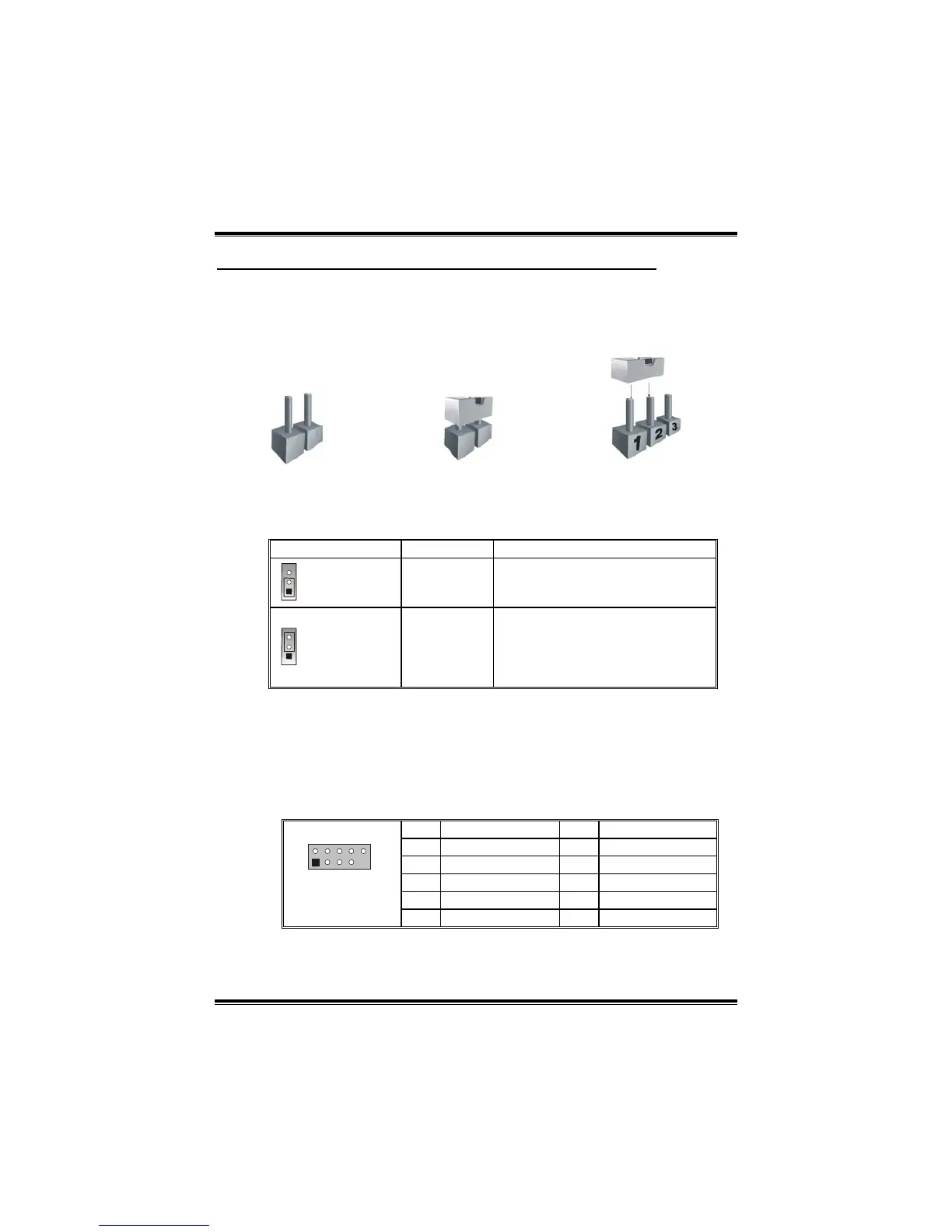
The illustration shows how to set up jumpers. When the jumper cap is
placed on pins, the jumper is “close”, if not, that means the jumper is
“open”.
Pin opened Pin closed Pin1-2 closed
3.2 DETAIL SETTINGS
JUSBV1/JUSBV2: Power Source Headers for USB ports
JUSBV1/JUSBV2 Assignment Description
1
Pin 1-2 close
+5V
JUSBV1: +5V for JKBMS1, JUSB1
and JUSBLAN1.
JUSBV2: +5V for JUSB3/4.
1
Pin 2-3 close
+5V Standby
Voltage
JUSBV1: JKBMS1, JUSB1 and
JUSBLAN1 are powered with +5V
standby voltage.
JUSBV2: JUSB3/4 are powered by
+5V standby voltage.
Note:
In order to support this function “Power-on system via keyboard and mouse”,
“JUSBV1/JUSBV2” jumper cap should be placed on Pin 2-3.
JUSB3/JUSB4: Front USB Headers
This motherboard provides 2 USB 2.0 headers, which allows user to
connect additional USB cable on the PC front panel, and also can be
connected with internal USB devices, like USB card reader.
Pin Assignment Pin Assignment
1 +5V (fused) 2 +5V (fused)
3 USB- 4 USB-
5 USB+ 6 USB+
7 Ground 8 Ground
1
2
10
JUSB3/JUSB4
9 Key 10 N/A
 Loading...