P4M800-M7 & P4M800-M7 A
17
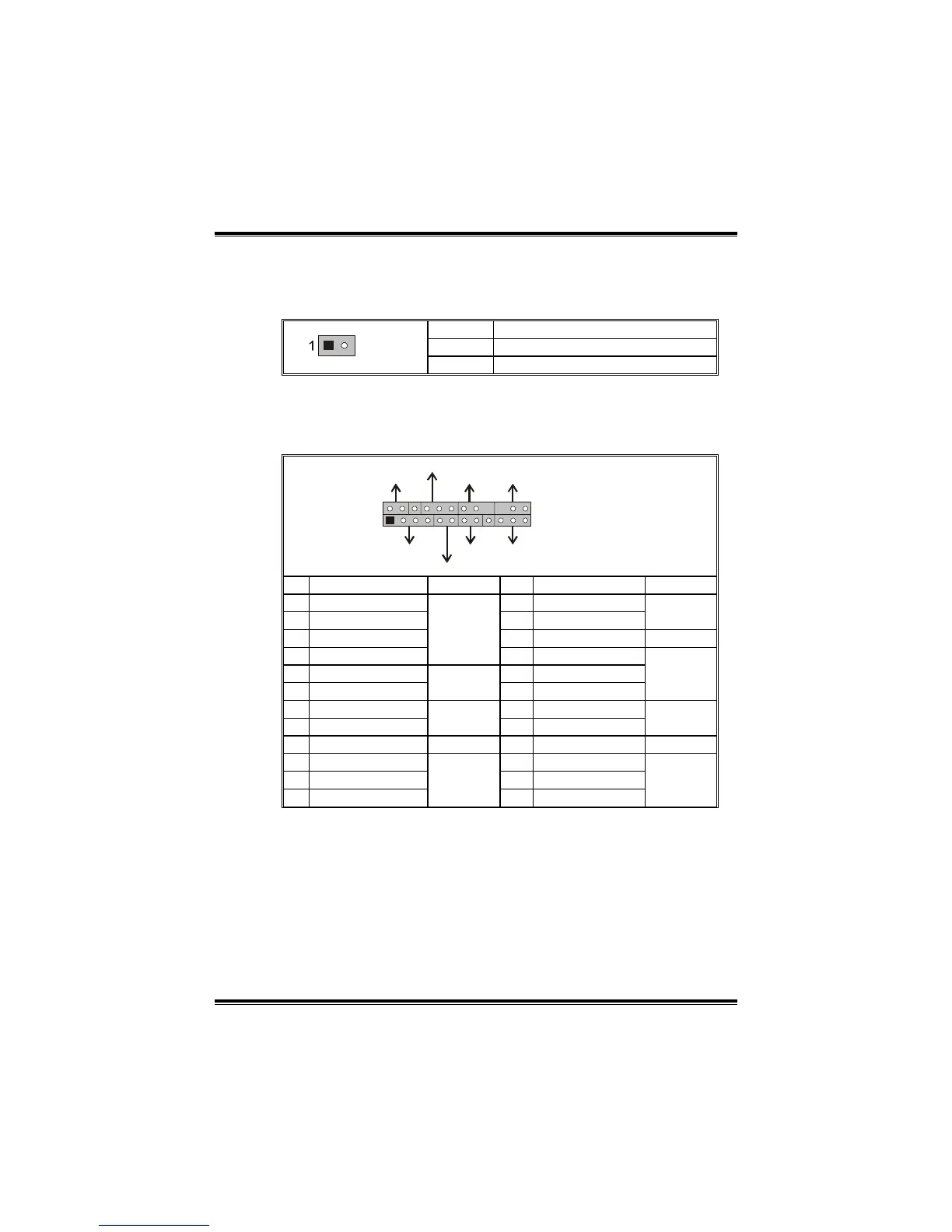
JCI1: Chassis Open Header
This connector allows system to monitor PC case open status. If the
signal has been triggered, it will record to the CMOS and show the
message on next boot-up.
Pin Assignment
1 Case open signal
JCI1
2 Ground
JPANEL1: Front Panel Header
This 24-pin connector includes Power-on, Reset, HDD LED, Power LED,
Sleep button, speaker and IrDA Connection. It allows user to connect
the PC case’s front panel switch functions.
1
2
23
24
SLP
PWR_LED
On/Off
IR
IR
RST
HLED
SPK
++
+
-
-
JPANEL1
Pin Assignment Function Pin Assignment Function
1 +5V 2 Sleep control
3 N/A 4 Ground
Sleep
button
5 N/A 6 N/A N/A
7 Speaker
Speaker
Connector
8 Power LED (+)
9 HDD LED (+) 10 Power LED (+)
11 HDD LED (-)
Hard drive
LED
12 Power LED (-)
Power LED
13 Ground 14 Power button
15 Reset control
Reset
button
16 Ground
Power-on
button
17 N/A 18 Key
19 N/A 20 Key
21 +5V 22 Ground
23 IRTX
IrDA
Connector
24 IRRX
IrDA
Connector
 Loading...