EasyManua.ls Logo

Biostar P4M890-M7 TE

Biostar P4M890-M7 TE
47 pages
Go to English
To Next Page IconTo Next Page
To Previous Page IconTo Previous Page
Loading...
P4M900-M7 SE/P4M890-M7 TE
13
CHAPTER 3: HEADERS & JUMPERS SETUP
3.1 HOW TO SETUP JUMPERS
The illustration shows how to set up jumpers. When the jumper cap is
placed on pins, the jumper is close, if not, that means the jumper is
open.
Pin opened Pin closed Pin1-2 closed
3.2 D
ETAIL SETTINGS
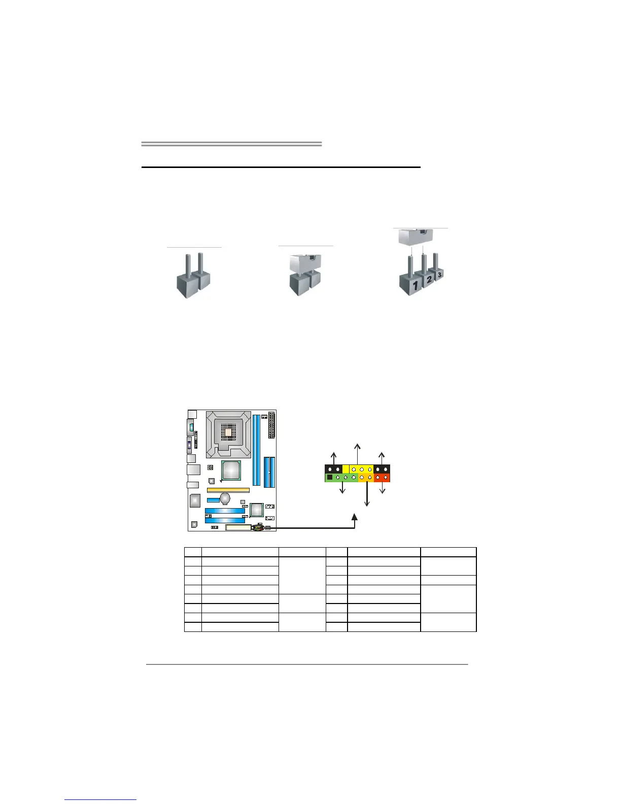
JPANEL1: Front Panel Header
This 16-pin connector includes Power-on, Reset, HDD LED, Power LED, Sleep
button and speaker connection. It allows user to connect the PC case’s front
panel switch functions.
1 8
16
SLP
PWR_LED
On/Off
RST
HLED
SPK
+ +
+
9
-
-
Pin
Assignment
Function
Pin
Assignment
Function
1
+5V
Speaker
Connector
9
Sleep control
Sleep button
2
N/A
10
Ground
3 N/A 11 N/A N/A
4
Speaker
12
Power LED (+)
Power LED
5
HDD LED (+)
Hard drive
LED
13
Power LED (+)
6
HDD LED (-)
14
Power LED (-)
7
Ground
Reset button
15
Power button
Power-on button
8 Reset control 16 Ground

Other manuals for Biostar P4M890-M7 TE

Related product manuals