
M
Mr. Julian FrancoSep 9, 2025
How to resolve error 1000 on Biotek Laboratory Equipment?
- Mmaria24Sep 9, 2025
To resolve error 1000, re-download software basecode and assays.
How to resolve error 1000 on Biotek Laboratory Equipment?
To resolve error 1000, re-download software basecode and assays.
What does error 0A00 mean on Biotek ELx808?
Error 0A00, 0A01 to 0A05 indicates that the lamp has failed since power-up. Check that the lamp is lit and replace it if necessary.
What to do if I get error 0900 on my Biotek ELx808?
Error 0900 can occur if the read chamber door has opened or closed relative to when the unit was powered on. Try closing the door and rebooting the reader to correct this. Also, check that the shrouds are installed and properly fastened, as electrical noise penetrating the measurement chamber can also cause this error.
Why am I getting error 0700 on my Biotek Laboratory Equipment?
Error 0700 can be caused by electrical noise penetrating the measurement chamber, ambient light leak, or a missing/loose filter. Check that the shrouds are installed and properly fastened, the plate chamber door is closed, and the filter wheel doesn’t have empty positions.
Why does my Biotek ELx808 show error 0800?
Error 0800 can be caused by electrical noise, ambient light, or filter issues. Ensure shrouds are fastened, the chamber door is closed, and the filter wheel has no empty positions.
What causes error 0300 0301 on Biotek ELx808?
Error 0300 0301 can be caused by a loose belt or a loose motor pulley, which may cause the carrier to ignore movement instructions. Check the carrier: the lamp may be out or blocked by a faulty filter wheel. Also, the filter wheel might be missing or loose, or a loose filter may be impeding its movement, so check the filter wheel.
What to do if Biotek ELx808 displays error A900?
Power instrument off, then back on.
What to do if the Biotek ELx808 lamp is out?
If the lamp is out, check that the lamp is lit when the unit is ON and replace the lamp if necessary. Also, ensure that the filters in the wheel match the filters programmed in the software, in case of a missing, defective, or misplaced filter or filter blank.
What does error 0D00 mean on Biotek Laboratory Equipment?
Error 0D00 indicates internal software corruption. Re-download software basecode and assays.
What does error 0500 mean on Biotek ELx808 Laboratory Equipment?
Error 0500 to 0506 indicates that all filter locations must have either a filter or a filter blank installed. Ensure that the filter wheel is installed properly.
Lists registered trademarks and company names.
Outlines limitations and responsibilities of the manufacturer.
Information on how to contact customer service and sales departments.
Contact details for technical assistance and service.
Specifies the designated purpose and limitations of the instrument.
Guidelines for ensuring accurate and reliable test results.
Important safety warnings regarding instrument operation and environment.
Details compliance with EMC directives for emissions and immunity.
Outlines compliance with low voltage safety directives.
Specifies compliance with FCC Class A limits for digital devices.
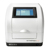
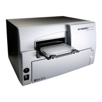
Describes the ELx808 as an eight-channel reader-assay system.
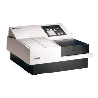
Differentiates between standard and incubator/UV models.
Lists the physical components and capabilities of the reader.
Details the functionalities and capabilities of the onboard software.
Lists the items included with the reader.
Lists additional items available for purchase.
Provides technical details like wavelength, filters, and measurement range.
Information on obtaining support and servicing for the instrument.
Instructions for registering the product with the manufacturer.
Procedures for unboxing and checking the instrument for damage.
Guidance on choosing a suitable location for instrument setup.
Steps for installing the filter wheel into the reader.
Instructions for setting the correct input voltage for the instrument.
Steps for connecting the instrument to a power source.
Instructions for connecting an optional printer to the reader.
Information on compatible printers and connection via parallel port.
Procedure for powering on the instrument and performing a system self-test.
How to ensure the software filter table matches physical filter locations.
Options for setting date, time, output, and read preferences.
Steps to set the date and time on the reader.
How to select report output devices and formats.
Options for choosing the format of printed reports.
Configuration of run-time prompts for plate and sample identification.
Steps to set up communication between the reader and Gen5 software.
Guide for connecting the reader to a computer and installing software.
Steps to verify instrument operation before initial use.
Procedures for preparing the instrument for shipping.
Guide to creating and running experiments using Gen5 software.
Overview of the reader's front panel interface and connectivity.
Explanation of the function of each key on the reader's keypad.
Describes the initial screens displayed during instrument power-up.
Overview of the main menu options and navigation.
A simplified method for quick assay programming and execution.
Steps for customizing and setting up assay protocols.
How to choose and load a predefined assay.
Procedure for naming or renaming an assay.
Configuration of assay parameters like method, mapping, formulas, and curve fits.
Defines the components of a reading method, including modes and parameters.
Selection of assay read modes: Endpoint, Kinetic, or Scan.
Setting a time delay before the first measurement is taken.
Setting the desired incubation temperature for assays.
Option to select single or dual wavelength readings for assays.
Selecting the appropriate filters for the assay measurement.
Setting the total number of reads or duration for kinetic assays.
Defining the time interval between consecutive kinetic reads.
Specifying the total number of kinetic measurements to be performed.
Setting the total time period for a kinetic reaction measurement.
Configuring the shaking parameters for the microplate.
Setting the duration for shaking the microplate.
Selecting the speed for microplate shaking.
Choosing the method for analyzing kinetic data.
Selecting the number of data points for kinetic analysis.
Defining the time at which a specific optical density is reached.
Setting up parameters for linear scanning across wells.
Defining how blanks, controls, standards, and samples are assigned to plate wells.
Method for assigning well locations, either automatic or manual.
Selecting the direction (column or row) for mapping wells.
Defining the direction for placing replicate samples.
Setting the starting point for automatic well mapping.
Choosing the blanking method to apply to the assay.
Explains different blanking methods like AIR, FULL, CONSTANT, ROW, COLUMN.
Entering a specific absorbance value for constant blanking.
Specifying how many blank wells are used in the assay.
Defining the physical location of blank wells on the microplate.
Setting the quantity of standards to be used in the assay.
Defining how many replicates of each standard are used.
Option to average standard replicates for curve calculation.
Entering the concentration values for each standard.
Instructions for reusing previously established standard curves.
Specifying the quantity of control samples used in the assay.
Defining the number of replicates for each control.
Specifying the physical location of control wells on the microplate.
Setting the total number of samples to be read.
Defining the number of replicates for each sample.
Specifying the physical location of sample wells on the microplate.
Setting up formulas for data validation, transformation, and classification.
Provides examples of blank, control, and assay validation formulas.
Selecting formula types: Cutoff, Transformation, and Validation.
Choosing the specific type of validation formula to enter.
Detailed steps for entering formulas using the reader's interface.
Specifying the number of valid controls or blanks for validation.
Calculating cutoff values for classifying sample results.
Defining a greyzone around the cutoff for equivocal results.
Assigning calls (POS, NEG, EQUIV) based on cutoff and greyzone values.
Changing absorbance data format for further processing.
Defining the scope (samples or all wells) for transformation formulas.
Screens for editing curve-fit types, outliers, axes, and extrapolation.
Selecting the method for fitting a curve to standard data points.
Excluding or including standards from curve-fit calculations.
Choosing the type of X and Y axes for curve plotting.
Deciding whether to extrapolate curve data for values outside the standard range.
Grouping up to 8 assays to run sequentially on a single plate.
The process of initiating and performing a microplate read.
Selecting the assay to be used for the plate read.
Handling prompts for sample information during a read.
Inputting the total number of samples for the assay.
Assigning a unique identifier to the microplate.
Entering unique identifiers for each sample.
The final step before starting the actual plate reading process.
How to generate and print various types of reports and assay lists.
Viewing and selecting results for specific plate IDs and assays.
Modifying standard outliers to improve curve-fit accuracy.
Printing the calculated results of an assay.
Printing the plate map showing well assignments for an assay.
Printing detailed settings for a specific assay.
Printing a list of all assays stored in the reader's memory.
Tips and best practices for achieving optimal reader performance.
Introduces IQ, OQ, and PQ procedures for the ELx808.
Defines recommended intervals for qualifying instrument performance.
Details various tests used for instrument qualification.
Describes the automated self-test performed by the reader.
Verifies the functionality and temperature control of the incubator zones.
Verifies the integrity of the reader's basecode software.
Tests mechanical alignment, accuracy, and repeatability using a special plate.
Checks read capabilities without a microplate.
Procedures for testing performance with liquid samples.
Steps for executing the qualification tests on the instrument.
Step-by-step guide for conducting Liquid Test 1.
Instructions for testing linearity, repeatability, and accuracy with liquid samples.
Procedure for executing the linearity test using prepared solutions.
Steps to calculate and verify the reader's repeatability.
Verifying consistency across different optical channels.
Optional test for linearity at 340 nm for UV models.
Steps to calculate and verify the linearity of the reader's measurements.
Defines tasks and frequencies for routine instrument maintenance.
Safety warnings and precautions before performing maintenance.
Instructions for cleaning the external surfaces of the instrument.
Procedures for inspecting and cleaning the reader's wavelength filters.
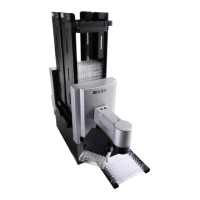
Maintenance steps for robotic models, including component lubrication.
Steps to adjust the robotic door motor after lubrication or reassembly.
Instructions for replacing the instrument's lamp and cleaning contacts.
Procedures for decontaminating the instrument before handling or shipping.
Step-by-step instructions for decontaminating the reader.
Introduces error code classifications and their implications.
Recommends performing a System Self-Test for diagnosis.
Defines terms relevant to understanding error code descriptions.
Lists general error codes and their probable causes.
Lists critical fatal errors requiring immediate attention.
Example of a report showing sample results with classification calls.
Example report illustrating the curve fitting results.
Example report displaying sample results and calls by column.
Example column report excluding sample-specific data.
Example report for assays run as part of a panel.
Detailed report of an individual assay's settings and parameters.
Example list of all programmed assays in the reader.
Example of programming an assay with transformations and cutoffs.
Example of programming an assay with a standard curve and cutoffs.
Typical results and interpretation ranges for the ANA assay.
Step-by-step guide for programming the ANA assay on the reader.
Calculating mean OD for duplicate assay readings.
Methods for plotting calibration curves, automatic or manual.
How to handle or remove anomalous data points from curves.
Determining autoantibody levels from calibration curves.
Details on assay calibration against reference standards.
Typical results and interpretation ranges for the Anticardiolipin assay.
Step-by-step guide for programming the Anticardiolipin assay on the reader.
How to identify the type of power input module installed in the reader.
Procedures for newer modules, including voltage and fuse adjustments.
Steps to adjust the voltage selector card for the correct input voltage.
Instructions for changing or replacing fuses in the power input module.
Procedures for older modules, including voltage and fuse adjustments.
Steps to adjust the voltage selector card for the correct input voltage.
Instructions for changing or replacing fuses in the power input module.
| Wavelength Selection | Filter-based |
|---|---|
| Light Source | Tungsten halogen lamp |
| Detector | Silicon Photodiode |
| Type | Microplate Reader |
| Detection Modes | Absorbance |
| Plate Types | 96-well microplates |
| Shaking | Yes |
| Interface | RS-232, USB |
| Filter Slots | 6-position filter wheel |