Directional RF Thruline® Wattmeter, Series 4410
9
Power Range Coverage
Each element is marked with its maximum power range capability, 10 W, 100 W,
1000 W, or 10000 W. Also stamped on the element nameplate is a factor
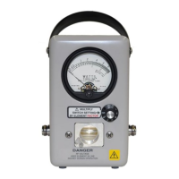
number. The power range switch on the Series 4410 Wattmeter determines the
full scale power range to be used. The available switch settings are 0.1, 0.3, 1, 3,
10, 30, 100, BATT, and OFF. This switch, when set on a numbered position and
multiplied by the element factor number, gives the full scale power value. For
example, if the element factor is 10 and a switch setting of 30 is opposite the
ARROW on the front face of the unit, 30 multiplied by 10 gives you 300 W full
scale. In this case, the lower scale (0-3) on the meter face will be used. If the
number opposite the ARROW is 10 and the element factor is 10, then 10 x 10 =
100, and 100 W will be the full scale reading and the upper scale (0-1) will be
used.
For reflected power readings the element is rotated 180° in the element socket
and the same system is used, however, a much lower switch setting may be
advantageous for better resolution.
Load Power
Where appreciable power is reflected, as with an antenna, it is necessary to
subtract the reflected from forward power to obtain load power. Power
delivered to and dissipated in an antenna is given by:
WL Wf Wr–=
Where:
WL = Power into Load
Wf = Forward Power
Wr = Reflected Power
This correction is negligible (less than 1 percent) if the load has a VSWR of 1.2 or
less.
The Series 4410 Thruline Wattmeter used with a Bird Termaline Load Resistor of
proper power rating forms a highly useful absorption wattmeter. Since the
reflected power will be negligible, it will be unnecessary to rotate the element
from the forward direction.