Directional RF Thruline® Wattmeter, Series 4410
21
Note: The wattmeter does not need to be connected to the cali-
bration setup for the five minute warm-up period.
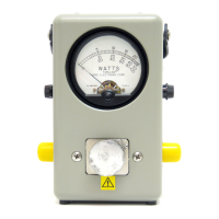
5. After the equipment has stabilized, check the battery in the wattmeter by
momentarily placing the range switch in the BATT position. The meter
pointer should travel well into the “BATTERY TEST” region of the meter
scale. If not, turn the unit off and replace the battery.
6. Return the switch to the “100” position.
7. Allow the unit’s internal circuitry to stabilize for another five minutes if the
battery was replaced.
8. Insert the calibration element into the wattmeter and rotate it in either
direction until it stops.
9. Recheck the sine wave generator for the proper 1000Hz ±100Hz output
settings, then readjust the amplitude as necessary until the voltmeter reads
a stable 1.591 ± 0.0005 volts.
10. Turn the 4410-070 calibration element 90° to short circuit the spring
contact in the line section to the line section body.
11. Set the range switch to the “1” position.
12. Adjust the sine wave generator’s output to the wattmeter’s calibration
voltage.
Note: This calibration voltage is recorded on a label inside the
instrument’s back cover. If no calibration voltage is listed, adjust
the sine wave generator’s output to 0.1591±0.00005 volts RMS.
13. Rotate the calibration element in either direction until it stops.
14. Adjust R26 until the meter pointer rests at ”1” on the upper scale.
Calibration is complete.
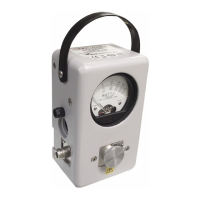
Figure 10 Calibration Potentiometer
Calibration
Potentiometer
A
H
l
X