SB-170-9 RUS
9
SB-170-9 25
5
.4.2 CM-SW-01
Standard for all CSW105 compressors
The compressor module integrates the entire electronic
periphery of the compressor: It allows monitoring the
essential operating parameters of the compressor: mo-
tor and discharge gas temperature, phase and rotation
direction monitoring, oil supply and application limits
and thus protects the compressor from operation under
critical conditions. For further information, see Tech-
nical Information ST-150.
NOTICE
The compressor module may be damaged or
fail!
Never apply any voltage to the terminals of CN7
to CN12 – not even for test purposes!
The voltage applied to the terminals of CN13
must not exceed 10V!
The voltage applied to terminal 3 of CN14 must
not exceed 24V! Do no apply voltage to the
other terminals!
The following components are completely installed and
wired in the state of delivery:
• Slider position indicator.
• Oil monitoring (OLC-D1).
• Solenoid valves for capacity control and V
i
.
• Discharge gas temperature sensor.
• Low pressure and high pressure transmitter.
Modification to these components or their wiring is not
required and should not be done without consulting
BITZER.
The following components are not installed and wired in
the state of delivery and need to be connected:
• Motor temperature monitoring (PTC sensor in motor
winding).
• Phase monitoring (in case of a phase failure or inad-
missibly high phase asymmetry).
The compressor module internally supplies voltage to
the peripheral devices (solenoid valves, oil monitoring
device and slider position indicator) and to the terminal
strips CN7 to CN12.
Please refer to the Technical Information ST-150 for in-
formation on all connections.
5
.4.3 SE-i1
This protection device with extended monitoring func-
tions can be used as an option for all HS.53 .. HS.85
compressors and CSH and CSW compressors.
Monitoring functions:
• Temperature monitoring.
• Monitoring of the PTC control circuit to detect any
short-circuit or line break/sensor failure.
• Rotation direction monitoring.
• Monitoring of phase failure and asymmetry.
• Monitoring of the maximum cycling rate.
For further information, see Technical Information
CT-110.
5
.4.4 SE-E2
Optional protection device for operation with frequency
inverter and soft starter (for a ramp time shorter than
1s).
• Dimensions and integration in the control identical to
SE-E1.
• Suitable for all CS. compressors.
• Monitoring functions are basically identical to those
of SE-E1. However, the SE-E2 monitors phase fail-
ure during the entire running time of the compressor.
For further information, see Technical Information
ST-122.
5
.4.5 Monitoring of the oil circuit
• For short circuits without liquid injection (LI) for addi-
tional cooling and for small system volume and small
refrigerant charge: Indirect monitoring with oil tem-
perature sensor (standard)
NOTICE
Lack of oil leads to a too high increase in tem-
perature.
Risk of damage to the compressor!
• For circuits with liquid injection (LI) for additional
cooling and / or for great system volume as well as
parallel compounding: Monitor oil level directly with
opto-electronic oil level monitoring (option), see
chapter Opto-electronic oil level monitoring OLC-D1-
S, page 26. The connection is on the compressor
housing, see chapter Connections and dimensional
drawings, page 14, position 8.
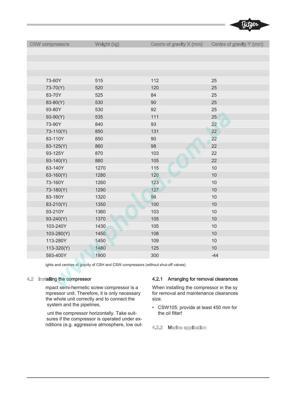
CSW compressors Weight (kg) Centre of gravity X (mm) Centre of gravity Y (mm)
CSW6583-40Y 360 34 22
CSW6583-50(Y) 365 39 22
CSW6593-50Y 360 42 22
CSW6593-60(Y) 365 46 22
CSW7573-60Y 515 112 25
CSW7573-70(Y) 520 120 25
CSW7583-70Y 525 84 25
CSW7583-80(Y) 530 90 25
CSW7593-80Y 530 92 25
CSW7593-90(Y) 535 111 25
CSW8573-90Y 840 93 22
CSW8573-110(Y) 850 131 22
CSW8583-110Y 850 90 22
CSW8583-125(Y) 860 98 22
CSW8593-125Y 870 103 22
CSW8593-140(Y) 880 105 22
CSW9563-140Y 1270 115 10
CSW9563-160(Y) 1280 120 10
CSW9573-160Y 1260 123 10
CSW9573-180(Y) 1290 127 10
CSW9583-180Y 1320 96 10
CSW9583-210(Y) 1350 100 10
CSW9593-210Y 1360 103 10
CSW9593-240(Y) 1370 105 10
CSW95103-240Y 1430 105 10
CSW95103-280(Y) 1450 108 10
CSW95113-280Y 1450 109 10
CSW95113-320(Y) 1480 125 10
CSW10593-400Y 1900 300 -44
Tab.2: Weights and centres of gravity of CSH and CSW compressors (without shut-off valves)
4.2 Installing the compressor
Every compact semi-hermetic screw compressor is a
motor-compressor unit. Therefore, it is only necessary
to install the whole unit correctly and to connect the
electrical system and the pipelines.
Install/mount the compressor horizontally. Take suit-
able measures if the compressor is operated under ex-
treme conditions (e.g. aggressive atmosphere, low out-
side temperatures, etc.). Consultation with BITZER is
recommended.
4
.2.1 Arranging for removal clearances
When installing the compressor in the system, arrange
for removal and maintenance clearances of sufficient
size.
• CSW105: provide at least 450 mm for the removal of
the oil filter!
4
.2.2 Marine application
With regard to marine applications, defined diagonal
mounting on the longitudinal axis of the ship can be ne-
cessary, see figure 3, page 10.