18
5.1.1 Using Two External Variable DC Voltage Sources
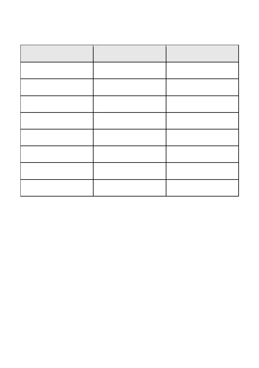
PIN FUNCTIONS REMARKS
1 Internal DC +5 V Less than 50 mA
2 Voltage Adjust 0 – 5 V
3 Current Adjust 0 – 5 V
4 Ground
5 Output OFF Short to Ground
6 N/A
7 N/A
8 N/A
Table 4 – Remote Connector Plug Pin Assignment for External Variable Voltage Sources
A variable external DC voltage source of 0 – 5 V is fed into the analog remote control
terminal to adjust the output voltage level of both Main and Auxiliary output.
WARNING: Do not input higher than 5 V, otherwise the overvoltage protection
(OVP) will be triggered.
1. Make sure the load is disconnected and the power supply is OFF.
2. Connect pin 2 to positive polarity of first external voltage source and pin 4 to
negative polarity of first external voltage source.
3. Connect pin 3 to positive polarity of second external voltage source and pin
4 to negative polarity of second external voltage source.
4. Turn the remote control ON/OFF switch to ON position.