Gas Pressure Fryer Operation
11
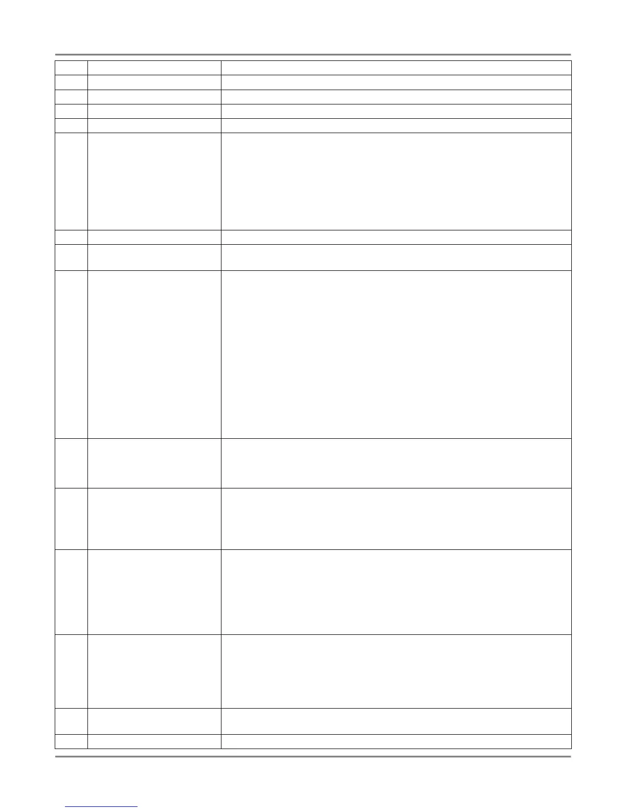
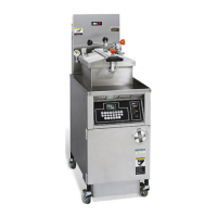
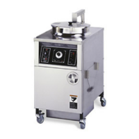
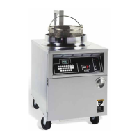
Item Description Function
1 Pressure Gauge Indicates the pressure inside the pot.
2 Spin Handle Used to tighten the lid to the pot once it is latched.
3 Pop Safety Valve lever Used to release pressure periodically to prevent the seat from sticking.
4 Computer Used to set and activate product programs.
5 Rocker Switch FILTER – When placed in this position, power is applied to the motor and
shorting is pumped into the pot directly or thru the fill hose.
OFF – When placed in this position, power is removed from both the pump
motor and gas system.
FRY – When placed in this position, power is supplied to the thermostat
and gas system.
6 Thermostat Knob Used to set the temperature of the shortening.
7 Thermostat Light Illuminates when the thermostat calls for heat. Extinguishes when the
shortening temperature is reached.
8 Analog Timer The analog timer consists of a light, dial, switch and buzzer described
below:
Light – Illuminates when the timer has been started and is counting down.
Cuts off when the timer is stopped.
Timer Dial – Used to set and display the time.
Timer Switch (ON/OFF) – Used to cut the timer on and off. To prevent
damage to the timer, always turn the timer switch OFF before setting the
timer dial.
Buzzer – A buzzer sounds when the timer counts down to 0. Placing the
timer switch to the OFF position will stop the buzzer.
9 High Limit Reset Switch If shortening inside the pot reaches an unsafe temperature, power is
automatically removed from the control panel and the gas system shuts
off. Pressing this switch returns power to the control panel and resets the
gas system.
10 Gas Control Valve Switch ON – Allows gas to flow when the FILTER/OFF/FRY switch is set to the
FRY position and the thermostat calls for heat.
OFF – Prevents gas flow regardless of FILTER/OFF/FRY switch and
thermostat settings.
11 Drain Lever DRAIN OPEN – When placed in this position, the drain valve opens and
shortening drains into the vat. Also power is removed from the control
panel and gas system.
DRAIN CLOSED – When placed in this position, the drain valve is closed
to prevent shortening from draining into the pot. Also power is restored to
the control panel and gas system.
12 Fill Lever FILL THRU POT – When placed in this position, shortening will be pumped
from the vat to the pot if the rocker switch is in the FILTER position.
FILL THRU HOSE – When placed in this position, shortening will be
pumped from the vat to the pot via a fill hose if the rocker switch is in the
FILTER position.
13 Pump Motor Reset Switch If the motor overheats while filtering, it will automatically shut off. Wait 15
minutes to allow motor to cool before pressing this switch.
14 Rinse Hose Connector Used to connect the Rinse hose for cleaning and refilling the pot.