® U.S. Registered Trademark
Copyright © 1999 Honeywell International Inc. • All Rights Reserved
INSTALLATION INSTRUCTIONS
69-1004-2
SV9401/SV9402/SV9403, SV9501/
SV9502/SV9503, SV9601/SV9602
SmartValve™
System Controls
APPLICATION
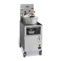
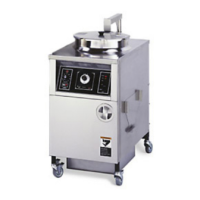
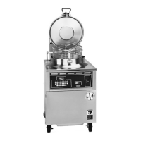
The SV9401/SV9402/SV9403, SV9501/SV9502/
SV9503, and SV9601/SV9602 SmartValve™ System
Controls combine gas flow control and electronic
intermittent pilot sequencing functions into a single unit.
This product family offers several different intermittent
pilot sequences for a wide range of applications. See
Table 1 for specific sequences available. The Q3450 or
Q3480 Intermittent Pilot hardware provides the low
voltage ignition, flame sensor, and pilot burner. This
system is suitable for application in a wide range of
gas-fired appliances including furnaces, rooftop
furnaces, boilers, unit heaters, infrared heaters, space
heaters, water heaters, decorative appliances, and
commercial cooking units. The specific application of the
SmartValve™ System is the responsibility of the
appliance manufacturer. See Table 2 for gas capacity
and thread sizes.
SPECIFICATIONS
WARNING
Fire or Explosion Hazard.
Can cause severe injury, death or property
damage.
The SV9401/SV9402/SV9403; SV9501/SV9502/
SV9503; SV9601/SV9602 provide direct
replacement only. Use the Y8610 to convert
standing pilot systems to electronic ignition
systems.
Ignition Sequences: See Table 1 for available ignition
sequences.
Body Pattern: Straight through. See Table 2 for inlet and
outlet specifications.
Capacity:
See Table 2 for available gas flow capacities.
Table 3 describes the acceptable ambient temperature
range for the SV9X01, SV9X02, and SV9X03
SmartValves.
Table 1. Ignition Sequence Description.
a
a
All times increase by approximately 20 percent when used at 50 Hz.
b
Pilot flow stops at end of ignition trial unless pilot lights and proves.
Electrical Ratings:
System Transformer: 40 VA minimum NEMA-rated
transformer. Control systems using SV9601, SV9602,
or other large secondary loads may require a larger
transformer. Refer to the appliance manufacturer
recommendation.
Voltage and Frequency: 24 Vac, 50/60 Hz.
Current draw at 24 Vac: 24V Hot: 1.25A nominal (1.5A
maximum) when igniter is powered.
24V Thermostat: See Table 4.
Electronic Fan Timer Output: 0.1A maximum at 24 Vac.
Output is 8 Vac less than thermostat input voltage at
0.1A draw.
Model Type Prepurge (sec) Ignition Trial Time
b
Auto Reset Time
SV9401/SV9501/SV9601 Continuous Retry — 90 seconds 5 minutes
SV9402/SV9502/SV9602 15 or 30 seconds
SV9403/SV9503 Single Trial with
Lockout
— 90 seconds N/A
69-1004-2.fm Page 1 Wednesday, November 5, 2003 10:49 AM