724-746-5500 | blackbox.com
Pa ge 11
Chapter 2: Overview
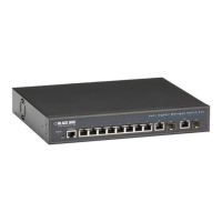
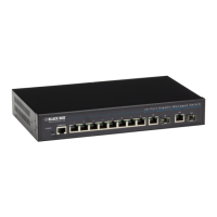
2.4.1 LPB2910A
1
2
5 4
6
7 8
9
3
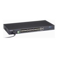
Figure 2-1. Front panel of the LPB2910A.
10
Figure 2-2. Back panel of the LPB2910A.
Table 2-1. LPB2910A components.
Number in Figures 2-1 and 2-2 Component in Figures 2-1 and
2-2
Description
1 (1) System LED Lights when system is active
2 (1) Mode/Reset button Press to select Mode or Reset
3 (1) PoE LED Lights when system is in PoE mode
4 (1) RJ-45 port Console port
5 (1) Link/Act/Speed LED Lights when switch is in Link/Act/Speed mode
6 (8) RJ-45 ports 10/100 /1000BASE-T ports
7 (8) Speed LEDs 10/100/1000 Mbps
8 (8) LINK/ACT LEDs Link/Activity LED: Blinking: activity on port;
Off: No link is established
9 (2) RJ-45/SFP combo ports 10/100/1000 RJ-45/100/1000 SFP combo ports
10 (1) 3-prong AC power socket Links to AC power cord
 Loading...