724-746-5500 | blackbox.com
Page 24
Chapter 5: Making Network Connections
5. Making Network Connections
5.1 Connecting Network Devices
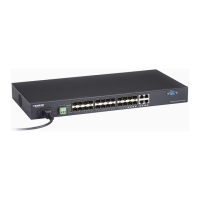
The switch is designed to be connected to 10, 100, or 1000 Mbps network cards in PCs and servers, as well as to other switches
and hubs. It may also be connected to remote devices using optional SFP transceivers.
5.2 Twisted-Pair Devices
Each device requires an unshielded twisted-pair (UTP) cable with RJ-45 connectors at both ends. Use Category 5, 5e or 6 cables
for 1000BASE-T connections, Category 5 or better for 100BASE-TX connections.
5.2.1 Cabling Guidelines
The RJ-45 ports on the switch support automatic MDI/MDI-X pinout configuration, so you can use standard straight-through
twisted-pair cables to connect to any other network device (PCs, servers, switches, routers, or hubs).
CAUTION: Do not plug a phone jack connector into an RJ-45 port. This will damage the switch. Use only twisted-pair cables with
RJ-45 connectors that conform to FCC standards.
5.2.2 Connecting to PCs, Servers, Hubs, and Switches
Step 1: Attach one end of a twisted-pair cable segment to the device’s RJ-45 connector.
Figure 5-1. Making twisted-pair connections.
Step 2: If the device is a network card and the switch is in the wiring closet, attach the other end of the cable segment to a
modular wall outlet that is connected to the wiring closet. (See the section “Network Wiring Connections.”) Otherwise,
attach the other end to an available port on the switch.
Make sure each twisted pair cable does not exceed 328 feet (100 meters) in length.
NOTE: Avoid using flow control on a port connected to a hub unless it is actually required to solve a problem. Otherwise,
back pressure jamming signals may degrade overall performance for the segment attached to the hub.
Step 3: As you make each connection, the Link LED (on the switch) corresponding to each port will light green (1000 Mbps) or
amber (100 Mbps) to indicate that the connection is valid.
5.2.3 Network Wiring Connections
A punchdown block is an integral part of many equipment racks. It is actually part of the patch panel. Instructions for making
connections in the wiring closet with this type of equipment follow.
Step 1: Attach one end of a patch cable to an available port on the switch, and the other end to the patch panel.
Step 2: If not already in place, attach one end of a cable segment to the back of the patch panel where the punchdown block is
located, and the other end to a modular wall outlet.
Step 3: Label the cables to simplify future troubleshooting. See “Cable Labeling and Connection Records.”
 Loading...