724-746-5500 | blackbox.com
Page 21
Chapter 4: Installing the Switch
4.7 Connecting to the Console Port
The RJ-45 serial port on the switch’s front panel is used to connect to the switch for out-of-band console configuration. You can
access the command-line-driven configuration program from a terminal or a PC running a terminal emulation program. The pin
assignments used to connect to the serial port are provided next.
Figure 4-8. Serial port (RJ-45) pinout.
Table 4-1. Wiring map for serial cable.
Switch's 8-Pin Serial Port Null Modem PC’s 9-Pin DTE Port
6 RXD (receive data) <—————— 3 TXD (transmit data)
3 TXD (transmit data) ——————> 2 RXD (receive data)
5 SGND (signal ground) —————— 5 SGND (signal ground)
NOTE: No other pins are used.
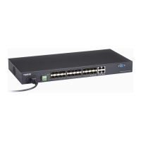
Figure 4-9. Plug in the console port.
The serial port’s configuration requirements are as follows:
• Default Baud rate—115,200 bps
• Character Size—8 Characters
• Parity—None
• Stop bit—One
• Data bits—8
• Flow control—none
 Loading...