724-746-5500 | blackbox.com
Page 15
Chapter 3: Network Planning
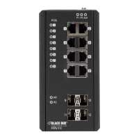
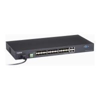
2.4.5 LED Indicators and their Functions
The table below describes the switch’s LED indicators and their functions.
Table 2-5. Port Status LEDs.
LED Indicator Condition Status
TP SPEED Green/Yellow Lit Green when TP link on 1000 Mbps,
Yellow when TP link on 10/100 Mbps
PoE (Link/ACT) Green Lit Green when PoE link with PD and supply power to PD
SFP SPEED Green/Yellow Lit Green when SFP link on 1000 Mbps,
Yellow when SFP link on 100 Mbps
Table 2-6. Mode Status LEDs.
LED Indicator Condition Status
Link/ACT/Speed Green Lit Green indicates all LED of each port are in Link/ACT/Speed mode.
PoE Green Lit Green when PoE link with PD and supply power to PD.
Table 2-7. System Status LED.
LED Indicator Condition Status
Power Green
OFF
Lit green when power is on,
Off when power is off.
2.4.6 Power Socket
An AC power socket is on the rear panel of the switch. Use an AC power cord (included) to power the switch.
2.4.7 Power over Ethernet (PoE)
Devices connected to the switch can be powered over the twisted-pair cable that links the devices to the switch. A powered
device (PD) provides power over the extra wires on the RJ-45 connector and cables.
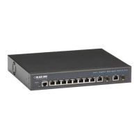
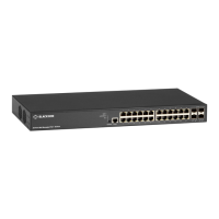
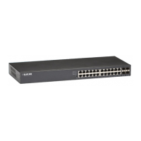
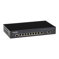
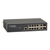
The LPB2910A, LPB2926A, and LPB2952A support PoE (802.3af) and PoE+ (802.3at) up to 30 W per port.
 Loading...