Installation
7
A tally connector is provided for use with switcher and automation systems. The 9-pin D connector wiring
description is printed on the rear of the unit showing contact closures to display red, green or blue tally
borders on each, independent monitor.
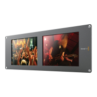
If SmartView Duo is to be installed high up in an equipment rack, you may wish to physically invert the LCDs
for the optimum viewing angle. The images on the LCDs will automatically flip to the correct orientation
when they sense an inversion. A number 02 size Pozidriv screwdriver is required to disconnect and
reconnect the faceplate from its rear assembly. This is a simple procedure and does not involve opening
the rear assembly.
SmartView Duo is 3 RU (rack units) high and less than an inch deep. You will need to leave enough space in
your equipment rack to install the SmartView Duo hardware.
SmartView Duo includes a universal power supply with international power socket adapters for all countries.
To stop power from being accidentally disconnected, a cable tie point is included just below the power
socket to lock down the power connection. You will need to provide a mains power socket for the universal
power supply.
 Loading...