CB9A-020 page 6
GENERAL INFORMATION
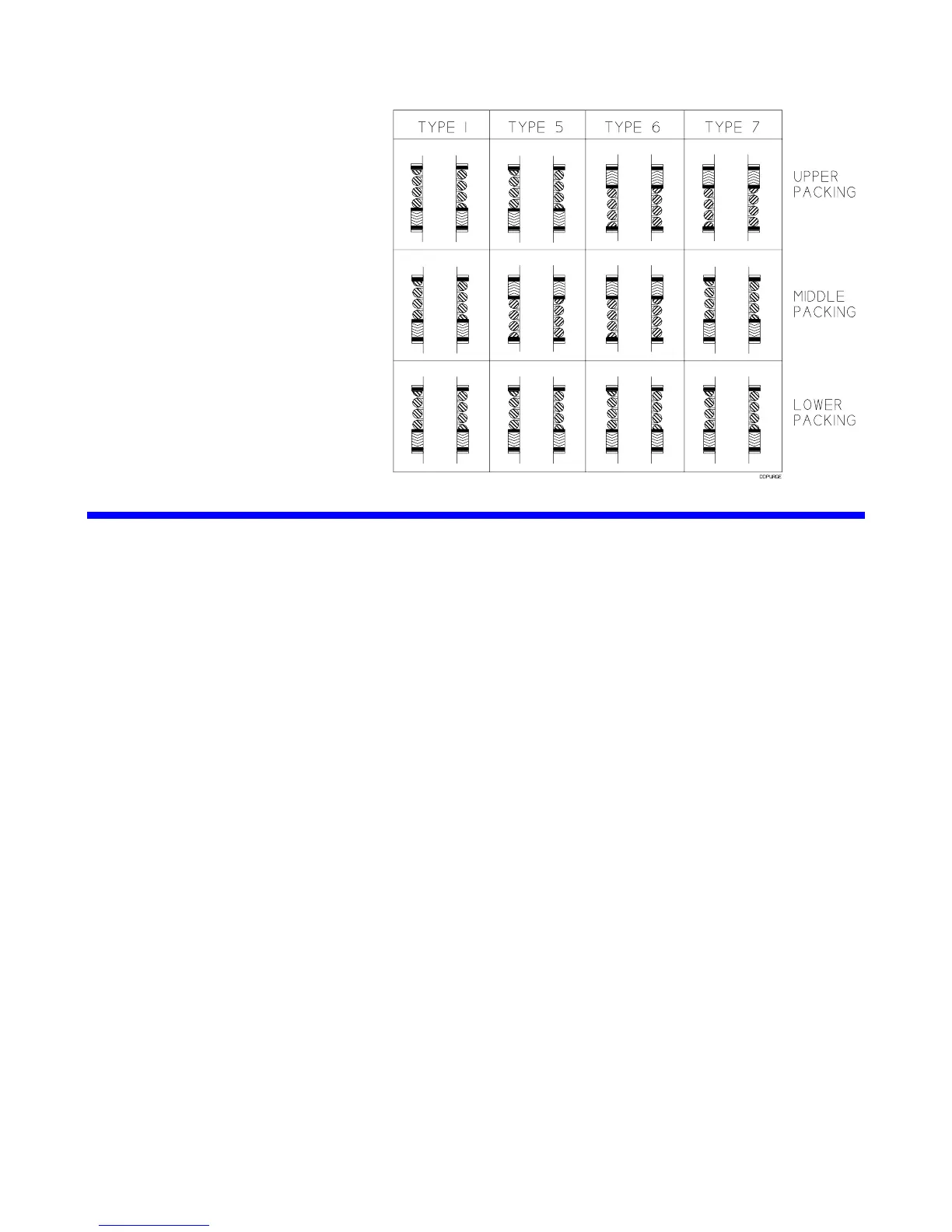
SEAL ORIENTATION –
ALL TRIPLE SEAL COMPRESSORS
OPTIONAL COMPONENTS
RELIEF VALVES
If a relief valve is not installed by the factory or the purchaser, one must be installed prior to compressor
startup. The relief valve should be installed in the discharge line between the compressor head and the first
block valve.
The type of relief valve should be appropriate to the application. Blackmer offers three relief valves for gas
compatibility: brass for LP-Gas service; aluminum for anhydrous ammonia; A.S.M.E. steel for both services,
and other applications.
The relief valve must be of a type, material and pressure rating suitable to the installation.
LIQUID TRAPS
Compressors handling gasses that contain condensates or other liquids must be protected from entry of the
liquid. LIQUID IN A COMPRESSOR CYLINDER CAN CAUSE DESTRUCTION OF THE COMPRESSOR.
Blackmer offers a variety of liquid traps. The most common variations include:
1. A non-code vessel fitted with a stainless steel float which will shut off the intake line to the compressor in
the event of an excessive liquid level. A vacuum breaking valve is provided on the liquid trap head in case
the trap closes and a vacuum develops between the compressor and the trap. A 1/4" manual drain valve
is provided.
2. The above trap is fitted with an additional port allowing for the use of an optional electric float switch which
provides protection to the compressor by stopping the compressor when a high liquid level is present in
the liquid trap. The electric float switch may be used with or without the mechanical float described above.
3. For additional protection, a larger ASME code stamped vessel is available. This liquid trap is typically
fitted with two electric float switches for both a high liquid level alarm and shut down signal, a relief valve,
and a 1" manual drain valve. Level gauges and automatic drain systems are available options.
TEMPERATURE SWITCHES
Temperature switches are highly recommended as high discharge temperature is a leading cause of premature
component failure and is often an early warning sign of impending problems.
Temperature switches should be installed with a thermowell as close to the compressor discharge as possible.
They should be set to actuate at a temperature just above the normal maximum operating temperature of the
compressor.