Blue Box - 27
It is recommended that a safety valve is installed that can discharge the
system in dangerous situations such as fire. The valve must be connected
to a vent pipe with a cross sectional area equal to or greater than the
valve and must be directed into a safe zone where people cannot be
injured.
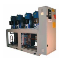
In all units with four compressors the water inlets and outlets of the
condensers, evaporators and heat recovery heat exchangers must be
connected together with a manifold (available as an option).
4.3 WATER PIPING CONNECTIONS
Unit water pipework must be installed in accordance with national and local regulation and codes.
Follow the recommendations below when designing the water piping circuit (refer to the diagrams included in this
manual).
- Piping should be connected to the unit with flexible joints, to avoid vibration transmission and allow for thermal
expansion (the same procedure should be adopted for the circulating pumps).
- The following devices should be located on the piping system:
- isolating/regulating valves, temperature gauges or thermometer pockets, pressure gauges or binder points
required for servicing operations.
- Serviceable mesh strainer, with a filtration level no larger than 1mm, located on the unit inlet to prevent
debris from entering the heat exchangers.
- vent valves, to be installed in the upper parts of the circuit, for air bleeding.
- expansion device with accessories for circuit pressurisation, water thermal expansion compensation and
system filling.
- unload valve and if necessary drainage tank for circuit emptying during maintenance and seasonal stop.