12
POOL FRAME ASSEMBLY continued
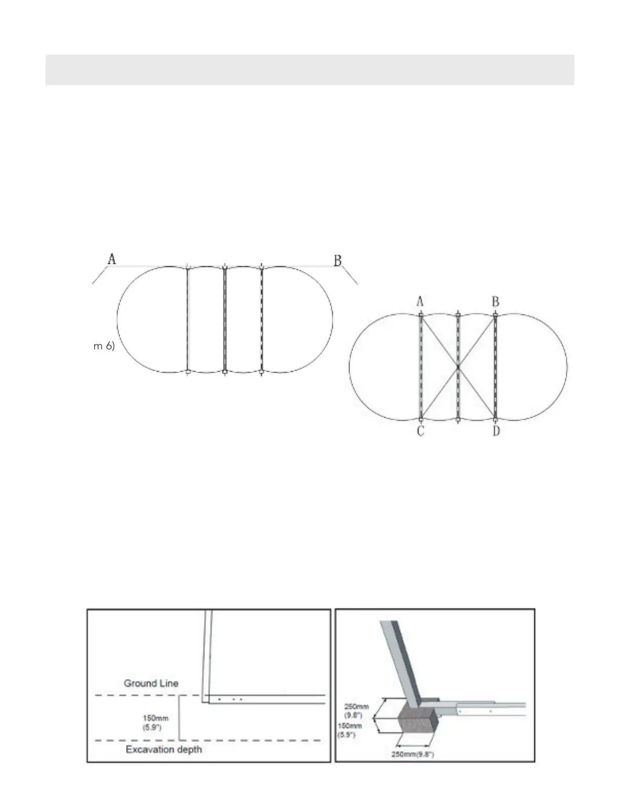
• To check the alignment of the assembled frames, hold a string along the back of the assembled
frames (the back of the L support) about 7-in - 8-in (200-mm) above the ground between two steel
pegs, position A and B (see diagram 6).
• If the L supports are not correctly aligned, they need to be adjusted back or forward until the back
of each L support is correctly aligned with the string line. Do this for both sides of the pool frame.
• Once the frame alignment is correct, check the diagonal measurements of the pool frame. Measure
the two intersecting axis to ensure that the two straight sections are parallel.
• The measurements of the points A to D and B to C must be equal (see diagram 7).
• When all the assembled frames components are in the correct position, spray paint a line on either
side of each assembled frame assembly all the way across the pool. This is to mark out the areas
to be excavated. When these areas have been marked out, the assembled frames can be removed
from the site.
• The marked areas should be excavated to a depth of 5.9-in x 5.9-in (150-mm x 150-mm) wide across
the pool from one side to the other with a length 9.8-in (250-mm) x width 9.8-in (250-mm) x depth
9.8-in (150-mm) excavation at each end for the positioning of the pre-cast concrete blocks or mixed
concrete pads (see diagram 8 and 9).
(Diagram 6)
(Diagram 7)
(Diagram 8) (Diagram 9)
Steel PegSteel Peg