33
H
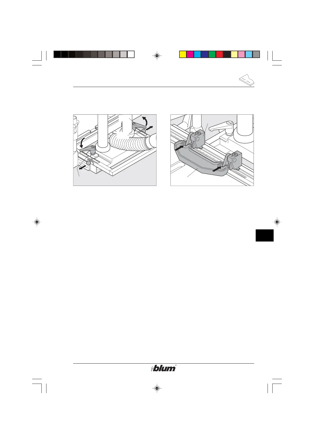
Drilling of line patterns
F15
F16
SY
L
L
D7
H3
7. Adjust fencing system (D4)
• Always place operation mode
switch to set up position and
disconnect the machine from it’s
electrical source (unplugged) before
performing any work on the drill
heads, fences, stops, or pneumatic
brake.
• Release clamping levers (F15).
• Pull out locating pin (F16), and
adjust fencing system (D4) to pos.
SY.
• Tighten clamping levers (F15).
With this adjustment, the distance
between fence and the centerline of
the drill bits is 37 mm.
8. Adjust positioning stops (D7)
(see section F - point 13)
9. Line boring
• Use Distance Gauge (H3) to set
additional positioning stops.
This will set a 3-3/4“ (96 mm) distance
between the stops and provide a
consecutive 1-1/4“ (32 mm) line boring
pattern.
%$0,1,35(66)$,G1US $0
 Loading...