CONTENTS
1 INTRODUCTION............................................... 2
1.1 General .................................................... 2
1.2 Function ................................................... 2
1.3 Product Identification ............................... 3
1.4 Air quality recommendations ................... 3
1.5 Safety Instructions ................................... 4
2 INSTALLATION ................................................ 5
2.1 Connections............................................. 6
2.2 General mounting instructions ................ 6
2.2.1 Mounting on rotary actuators .................. 6
2.2.2 Mounting on linear actuators ................... 6
2.3 Installation instructions
for rotary actuators .................................. 7
2.3.1 Double acting........................................... 7
2.3.2 Single acting ............................................ 7
2.4 Installation instructions
for linear actuators ................................... 8
2.4.1 Double acting........................................... 8
2.4.2 Single acting ............................................ 8
2.5 Cam ......................................................... 9
2.5.1 Adjustments ............................................. 9
2.5.2 Cam specifications .................................. 9
2.6 4-20 mA connection ................................ 10
2.6.1 Connecting the control signal .................. 10
2.6.2 Checking the control signal ..................... 10
2.6.3 Bench test with calibrator ........................ 10
2.7 Calibration ............................................... 11
3 MAINTENANCE ............................................... 12
3.1 Front cover and Indicator ......................... 12
3.2 Pilot valve ................................................ 13
3.3 I/P-converter, type EA1 ........................... 14
3.4 Filter ......................................................... 15
3.5 Membrane ............................................... 16
3.6 Feed back spring, changing .................... 17
3.7 Feed back spring, disassembly ............... 18
3.8 Balance arm ............................................ 19
3.9 Guide arm, changing ............................... 20
3.10 Guide arm, disassembly .......................... 21
3.11 Drive shaft ............................................... 22
3.12 Drive ........................................................ 23
3.13 Safety valve ............................................. 24
4 CONVERTING .................................................. 25
4.1 V100P to V100E ...................................... 25
5 SPARE PARTS ................................................. 26
5.1 Exploded drawing .................................... 26
5.2 Spare parts list ........................................ 27
6 TECHNICAL INFO ............................................ 28
6.1 Specifications .......................................... 28
6.2 Dimensions .............................................. 29
1
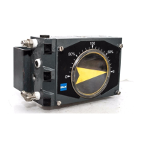
V100 Positioner