BMG LABTECH PHERAstar FS Operating Manual
2009-09-22 0471B0001A 11/26
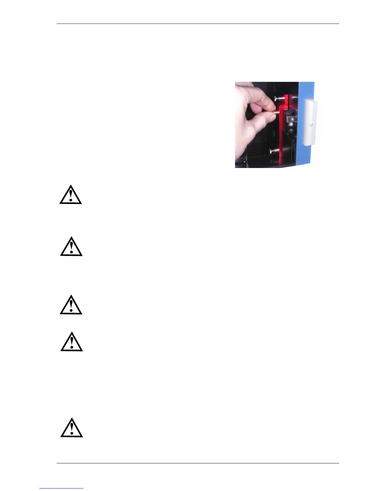
3.1.4 Inserting and Locking the Optic Module Transport System Protection Plate
Upon closing the software or pushing the plate carrier in/out button for more than three seconds (see figure
10), the Optic Module transport system will move into its respective reference and lock position. Hereafter,
turn off the PHERAstar FS and you can position the red protection plate (with the spring loaded screws
connected to it) in the position shown in figure 9. First position and fix (finger tight) the middle positioned
screw; after that position and fix the two other screws.
Figure 9: Carefully position the red protection plate and start fixing
the screw in the middle position, thereafter the other two screws
Both the plate carrier transport and the optic module transport needs to be locked
before moving or shipping the reader.
3.2 Power and Communication Connections
Check that the power switch on the back of the instrument is in the "OFF" position.
Inspect the voltage information on the label next to the power switch (see figure 4) to ensure that it
corresponds to the local main power specifications. Also make sure the power cable is grounded. Hereafter,
connect only the power cable to the instrument.
In order to make a ‘Connection check’, the Control Software needs to be installed before
connecting the USB cable to the instrument. Please refer to the software manual part of
this binder to install the software and how to perform a connection check.
Make sure the plate carrier and the optic module transport systems are unlocked (see
chapter 3.1.1 and 3.1.3 above). Put the power switch in the “ON” position.
Connection check
Connect the USB cable to the USB port labelled “PC” located on the back of the PHERAstar FS and to the
USB port on the PC. If a Stacker is included in the package, please see section 4.7 below. Once the USB
cable is installed open the PHERAstar FS Control Software and perform the connection check.
Only connect a computer that corresponds to EN 60950 and UL 1950 for data processing
instruments.