BMG LABTECH PHERAstar FS Operating Manual
2009-09-22 0471B0001A 13/26
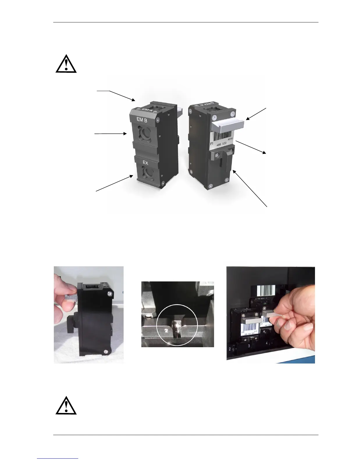
Figure 13: Hold the optic
module by the handle
Figure 14: The groove of
the optic module transport
system
Figure 15: When installing or
removing the optic module, hold
the handle and move it up and out
4.4 Installing and Changing Optic Modules
All PHERAstar FS readers can be equipped with six optic modules. Five optic modules can be exchanged
and one optic module (Luminescence) is preinstalled.
In case of shipment or moving the PHERAstar FS, it is important to remove the optic
modules from the optic module transport.
Figure 12: Optic module, front view and side view
When the PHERAstar FS is in its permanent position and powered ON, the optic modules can be installed.
The PHERAstar FS has five positions for optic modules. Once the optic module door has been opened the
optic module transport will automatically move to a position where it can be accessed. Install the optic
modules by holding it by the handle (figure 13) and then position the optic module positioning pin in the
groove (figure 14 and figure 15).
Be careful not to touch any optical surfaces while handling the optic modules.
The various types of optic modules are described in more details in sections 4.5.1 to 4.5.4.
Optic module
positioning pin
Excitation
Emission
channel B
Handle to hold
optic module
Emission
channel A
Label with bar-code,
measurement
principle,
wavelengths and
batch-nr. code