OZONE ANALYZER BMT 964 Manual, Rev. 04/2021
47
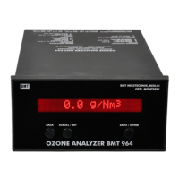
Electric Connections
Signal connector: 1
current signal, output
4 - 20 mA high
2
current signal, output
4 - 20 mA low
3
voltage signal, output
0 - 10 V high
4
voltage signal, output
0 - 10 V low
5 Auto Zero, input high (+24 VDC, 18 mA)
6 Auto Zero, input low
7
Error Contact, output
} open on error
8
Error Contact, output
9 WARM (DH5) open on error
10 Output contacts, Common for pins 9, 12, 13, 14, 15, 16
11 Cable Shield
(conn. soldering side) 12 Lamp Low, output open on error
13 Low Limit Alarm, output opening or closing
14 High Limit Alarm, output opening or closing
15 Cuvette Dirty, output open on error
16 LOW FLOW (SGP5) open on error
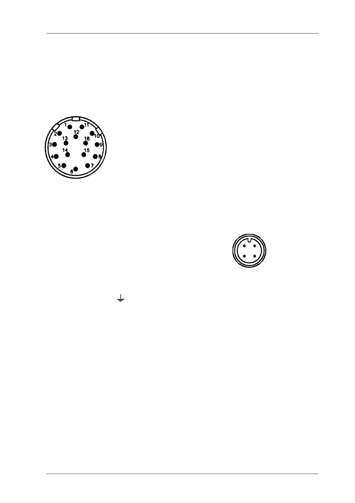
RS-232 connector: 1 Cable Shield
2
TxD (from BMT 964 C)
3
RxD (to BMT 964 C)
(screw terminal
4 Signal GND (= analog GND) side)
Mains connector: 1 mains
} (100 to 240 VAC, 50/60 Hz, 200 VA)
2 mains
3 (free)
Protective Ground
For further description of the functions and properties of the cabinet version please refer to the
main part of the manual.
2
1
3
4