OZONE ANALYZER BMT 964 Manual, Rev. 04/2021
49
SENSOR enclosure with dry air, in case the water temperature is below the ambient, to prevent
condensation of water vapor on the cooled inner surfaces.
Materials in contact with the ozonised water are only quartz glass, and PFA (sapphire, PFA and
PTFE in the HF version). The connections between the PFA tubing and the quartz cuvette are
secured with special, spring loaded, uniform peripheral pressure clamps.
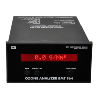
The instrument must be mounted with the arrow on the front panel pointing upwards!
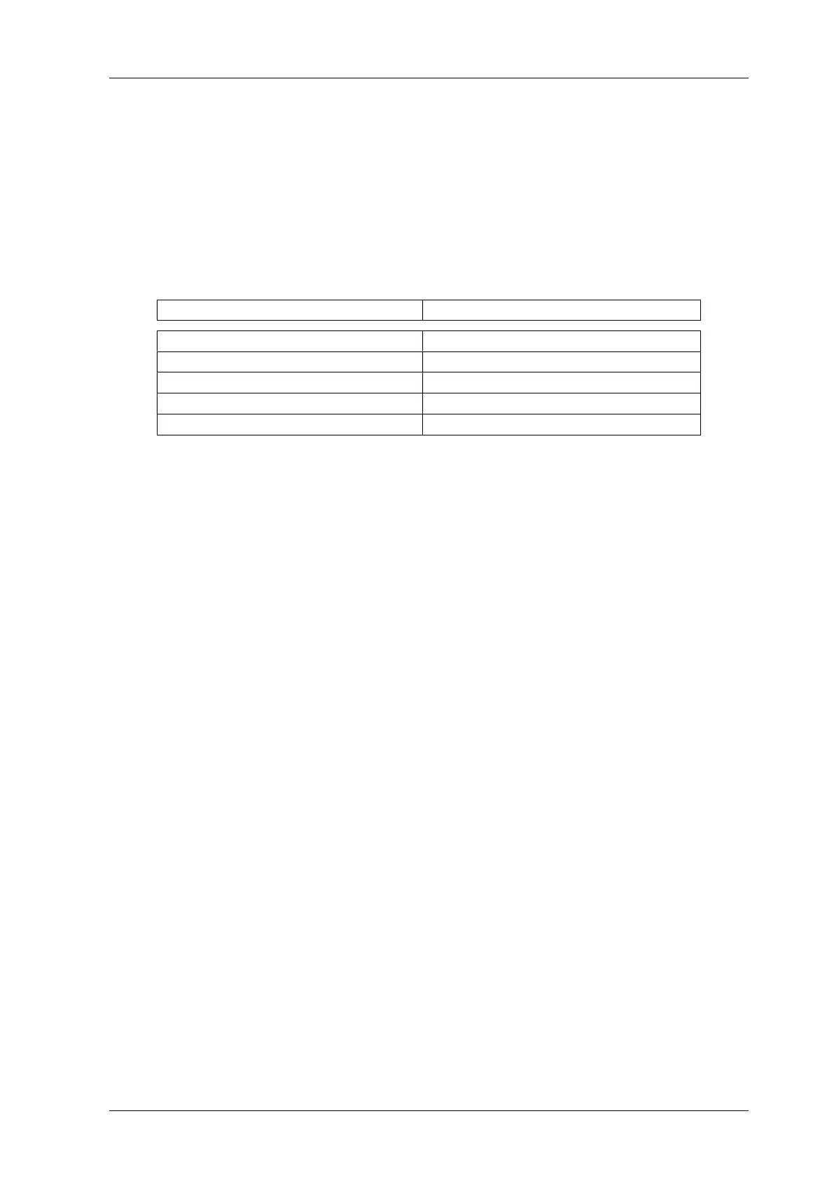
Measurement ranges and associated maximum pressure:
BMT 964 AQ BMT 964 AQ/HF
10 g/m
3
(10 ppm, max. 1 bar g) 10 g/m
3
(10 ppm, max. 2.5 bar g)
- 20 g/m
3
(20 ppm, max. 2.5 bar g)
50 g/m
3
(50 ppm, max. 4 bar g) 50 g/m
3
(50 ppm, max. 2.5 bar g)
100 g/m
3
(100 ppm, max. 4 bar g) 100 g/m
3
(100 ppm, max. 4.0 bar g)
150 g/m
3
(150 ppm, max. 6 bar g) 150 g/m
3
(150 ppm, max. 4.0 bar g)
Some ranges may be ordered compatible with up to 20% hydrofluoric acid (BMT 964 AQ/HF,
see table). Pressure and temperature compensation (which is standard in our gas analyzers) is not
provided because it is not necessary here. Proof pressure is listed above.
We recommend a water flow rate between 100 and 300 cm
3
/min. Pressure head (with 2 x 50 cm
PFA tubing, 4 mm ID, connected to the inlet and outlet fittings) is about 7.5 cm H
2
O for a flow
rate of 100 cm
3
/min, 18 cm H
2
O for 200 cm
3
/min, and 33 cm H
2
O for 300 cm
3
/min. The
OZONE-IN-WATER SENSOR usually is used as a bypass to a small flow resistance in a large
diameter main PFA tubing line. The SENSOR then should be positioned beneath the main tub-
ing to let gas bubbles bypass the SENSOR.
If a throttle (flow resistance) is installed to control the flow rate through the OZONE-IN-
WATER SENSOR, this throttle must be positioned behind the sensor (never in front of it!), be-
cause gas could bubble out of the water after a pressure drop and disturb the measurement.
When the fluid to be measured is at a temperature lower than the ambient, flushing of the in-
strument with clean dry air (or nitrogen) is necessary to prevent condensation of water. Flow rate
of the dry gas should be about 0.2 l/min.
As long as the cuvette of the SENSOR remains clean, zeroing of the instrument is not necessary
for weeks, or even for months. But for safety, zero reading should be checked on a regular basis
by applying water with zero ozone concentration. For checking zero reading no other method
is possible. When the cuvette is filled with water having zero ozone concentration, zeroing has to
be initiated by pressing the push button ZERO at the optional REMOTE DISPLAY
BMT 964 RD, or via the binary input at pins 5 and 6 of the signal connector, or RS-232 (for de-
tails see the main part of the manual).
The REMOTE DISPLAY is connected to its own 12-pole connector. The 16-pole Signal Con-
nector is free for access to all signal inputs and outputs. The analyzer must be ordered as
BMT 964 AQ/RD in order to operate together with a REMOTE DISPLAY.