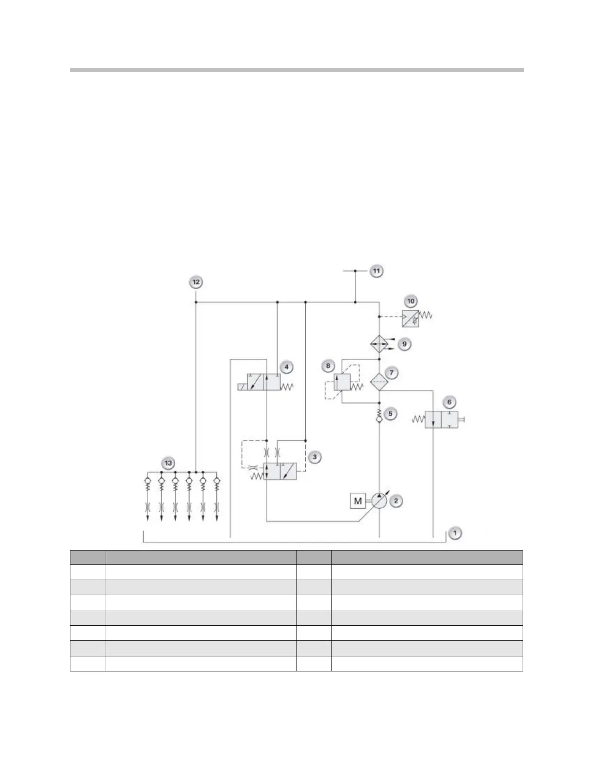
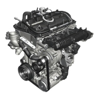
The oil pressure generated by the oil pump (2) is delivered to the engine’s lubricating
points and hydraulic actuators. This system uses oil pressure feed back to control the
desired operating oil pressure. For this purpose, the oil pressure downstream of the oil
filter (7) and engine oil-to-coolant heat exchanger (9) is adjusted by the DME (map-con-
trolled) via the pressure control valve (4) to the pressure control valve (3).
The actual generated oil pressure is registered by the oil pressure sensor (10) and
recognized by the engine management.
In the event of an electrical malfunction, the oil pressure is set to the default control
setting. The pump compression springs are allowed to expand, moving the slide valve to
its maximum oil pressure position.
Hydraulic diagram of the N53 engine oil circuit with electronic pressure control
Note: The N53 hydraulic circuit diagram shown is for explanation of the oil
pressure control only, and does not apply directly to the N55 engine.
25
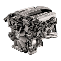
N55 Engine
Index Explanation Index Explanation
1
Oil Pan
8
Filter By-pass valve
2
Volume controlled oil pump
9
Engine oil to coolant heat exchanger
3
Pressure regulating valve
10
Oil Pressure sensor
4
Electro-hydraulic pressure regulating valve
11
Lubricating points, cylinder head
5
Non-return valve
12
Lubricating points, engine block
6
Outlet valve at the filter
13
Oil spray nozzles, piston crowns
7
Oil filter