9
EN
2.3.2 Mounting with back cover
According to the model of the clock make the cut-out following le dimensions listed in table below
Dimensions in mm
a) Insert the back cover in the cut-out tn order to mark the position of the mountig screws.
b) Remove the back cover and drill 2 holes Ø 6 mm ( ) to insert the wall plugs.for the back
cover mounting
c) Drill 4 holes Ø 10mm ( ) to make room for the back cover clock mounting rivets.
d) Feed the power cable, the synchronisation cable and the keypad cable throught the cut-out and
cable glands of the back cover.
e) Fix the back cover to the wall with the 2 screws Ø 4mm
f) Connect the clock, adjust the brightness (page 7) and set the time (refer to page 10)
g) Fix the clock to the back cover with the 4 screws Ø 4mm
CAUTION: do not fit a DHF clock in a metal partition or equivalent.
Installation with back cover
A B C D E
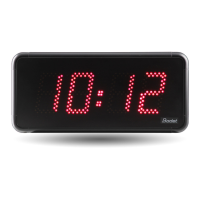
Style 5
46
275 241 68 107
Style 5S 400 365 68 107
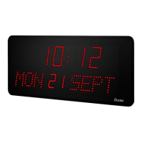
Style 7 325 291 85 117
Style 7S 440 404 85 123
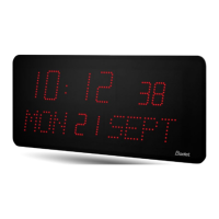
Style 7 Date 365 331 200 308
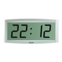
Style 10 424 406 100 165
Back cover mounting screws
X
Y
Y
X
Y